3.7. Creating a URDF with an UR5 robot and a custom end-effector
3.7.1. Export your meshes
In ROS, robot link (and end-effector) geometry is defined with 2 different meshes: visual and collision. The visual mesh represents how the robot looks like and the collision mesh is used for collision detection. You could have the same collision and visual meshes, but a coarse collision mesh saves some processing time while performing collision checks. Also, you might want to built the collision geometry slightly larger than the visual geometry to guarantee for safe zones.
Before exporting, please position your end-effector such that the connection point to the flange (tool0) is in (0,0,0). The geometry of your end-effector has to be defined in meters. Then export both visual and a collision meshes of your end-effector in a ROS-friendly format, like .stl or .obj (see below).
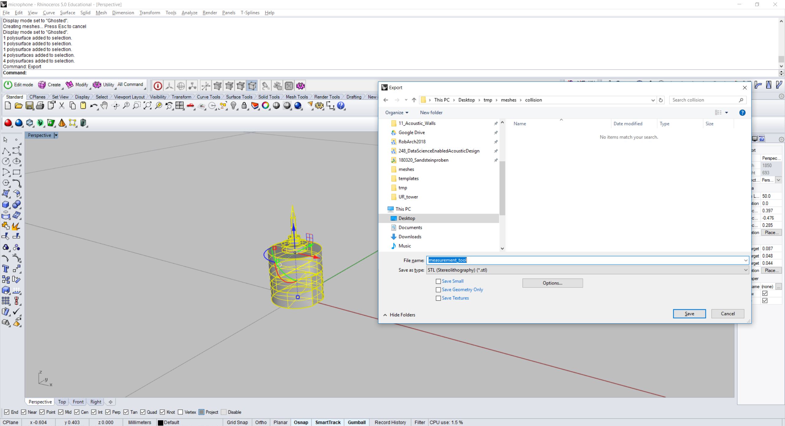
Screenshot of exporting a tool geometry from Rhino3D positioned in (0,0,0).
3.7.2. Prepare your catkin workspace
Open your command prompt and go to your home directory:
cd ~
If not yet there, make a new catkin workspace for all your robotic setups:
mkdir -p ~/robotic_setups/src
cd ~/robotic_setups
catkin_make
Then go to your src folder and make a package with your new setup
ur5_with_measurement_tool:
cd ~/robotic_setups/src
catkin_create_pkg ur5_with_measurement_tool
This will create a ur5_with_measurement_tool folder which contains a
package.xml and a CMakeLists.txt. Then open package.xml and add the
following lines after the line <buildtool_depend>catkin</buildtool_depend>.
<buildtool_depend>catkin</buildtool_depend>
<test_depend>roslaunch</test_depend>
<build_export_depend>joint_state_publisher</build_export_depend>
<build_export_depend>robot_state_publisher</build_export_depend>
<build_export_depend>rviz</build_export_depend>
<build_export_depend>xacro</build_export_depend>
<exec_depend>joint_state_publisher</exec_depend>
<exec_depend>robot_state_publisher</exec_depend>
<exec_depend>rviz</exec_depend>
<exec_depend>xacro</exec_depend>
Optionally, modify email and licence, version tags.
Then create 4(+2) folders: launch, rviz, urdf and meshes (with visual and collision folders):
mkdir ~/robotic_setups/src/ur5_with_measurement_tool/{launch,rviz,urdf,meshes,meshes/visual,meshes/collision}
Copy your meshes into meshes/visual and meshes/collision.
3.7.3. Create xacros and generate urdf
Rather than writing urdf files directly, it is more convinient to write xacro
files from which urdfs are generated. As its name implies, xacro is a macro
language. The language allows to use constants, to perform simple math
operations and to parameterize macros simply by using ${}.
Note
For more examples, have a look at the Xacro tutorials on the ROS Wiki.
Go to the urdf folder and create a xacro file for your end-effector with the text editor of your choice (e.g. pico):
cd ~/robotic_setups/src/ur5_with_measurement_tool/urdf
pico measurement_tool.xacro
Paste the following into the file:
<?xml version="1.0" encoding="utf-8"?>
<robot xmlns:xacro="http://ros.org/wiki/xacro">
  <!-- Here we define the 2 parameters of the macro -->
  <xacro:macro name="measurement_tool" params="prefix connected_to">
    <!-- Create a fixed joint with a parameterized name. -->
    <joint name="${prefix}measurement_tool_joint" type="fixed">
      <!-- The parent link must be read from the robot model it is attached to. -->
      <parent link="${connected_to}"/>
      <child link="${prefix}measurement_tool"/>
      <!-- The tool is directly attached to the flange. -->
      <origin rpy="0 0 0" xyz="0 0 0"/>
    </joint>
    <link name="${prefix}measurement_tool">
      <visual>
        <geometry>
          <!-- The path to the visual meshes in the package. -->
          <mesh filename="package://ur5_with_measurement_tool/meshes/visual/measurement_tool.stl"/>
        </geometry>
      </visual>
      <collision>
        <geometry>
          <!-- The path to the collision meshes in the package. -->
          <mesh filename="package://ur5_with_measurement_tool/meshes/collision/measurement_tool.stl"/>
        </geometry>
      </collision>
    </link>

    <!-- TCP frame -->
    <joint name="${prefix}tcp_joint" type="fixed">
      <origin xyz="0 0 0.116" rpy="0 0 0"/>
      <parent link="${prefix}measurement_tool"/>
      <child link="${prefix}tcp"/>
    </joint>
    <link name="${prefix}tcp"/>

  </xacro:macro>
</robot>
3.7.3.1. Explanation
The end-effector consists of one fixed joint (that will be attached to the tool0 of the robot), one link with geometry (the tool geometry), one fixed joint (the tcp joint, defining the TCP frame) and the tcp link without geometry.
We define a parameterized macro with 2 parameters (${prefix}, ${connected_to}) because
maybe once we want to attach the tool to a different robot with a different
flange name or, if we once want to use the end-effector twice in the same urdf
we would need to use both with different prefixes to distinguish them.
Whatever is defined like ${} will later be replaced when generating the
urdf.
Now we create a new xacro file, which combines the ur5 with the end-effector:
pico ur5_with_measurement_tool.xacro
Paste the following:
<?xml version="1.0"?>
<robot xmlns:xacro="http://ros.org/wiki/xacro" name="ur5_with_measurement_tool">

  <!-- ur5 -->
  <xacro:include filename="$(find ur_description)/urdf/ur5.urdf.xacro" />
  <!-- end-effector -->
  <xacro:include filename="measurement_tool.xacro" />

  <!-- ur5 -->
  <!-- The ur5 xacro must be included with passing parameters -->
  <xacro:ur5_robot prefix="" joint_limited="true"/>
  <!-- end-effector -->
  <!-- Here we include the end-effector by setting the parameters -->
  <!-- TODO: check end-effector link name of robot -->
  <xacro:measurement_tool prefix="" connected_to="tool0"/>

  <!-- define the ur5's position and orientation in the world coordinate system -->
  <link name="world" />
  <joint name="world_joint" type="fixed">
    <parent link="world" />
    <child link="base_link" /> <!-- TODO: check base_link name of robot -->
    <origin xyz="0.0 0.0 0.0" rpy="0.0 0.0 0.0" />
  </joint>
</robot>
To define the link name we want to attach the tool to, we search in the robot’s xacro file the last link which does not have a geometry anymore. For example, for a 6-axis robot the last joint is joint6, joint6 has the child link link6 which contains the geometry. Usually, link6 is parent to another joint, which child link (without geometry) is the link we attach the tool to (usually named with tool0).
tool0
The tool0 frame (pronounced: ‘tool-zero’) shall match exactly an all-zeros TCP configuration as defined on the robot controller. For most controllers, this is equal to an unconfigured TCP, which lies on the physical robot’s mounting flange.
base_link
The base_link shall be positioned in the logical base position (oriented by convention, z-axis up, x-axis forward). This frame name is by ROS convention. Typically this frame is the first frame of the robot tied to the first link.
To define the base_link name we search in the robot’s xacro file the link which is never child to a joint (first link).
Now create the urdf.:
rosrun xacro xacro --inorder -o ur5_with_measurement_tool.urdf ur5_with_measurement_tool.xacro
This will create ur5_with_measurement_tool.urdf in the directory.
You can also check the urdf with:
check_urdf ur5_with_measurement_tool.urdf
This will output:
robot name is: ur5_with_measurement_tool
---------- Successfully Parsed XML ---------------
root Link: world has 1 child(ren)
    child(1):  base_link
        child(1):  base
        child(2):  shoulder_link
            child(1):  upper_arm_link
                child(1):  forearm_link
                    child(1):  wrist_1_link
                        child(1):  wrist_2_link
                            child(1):  wrist_3_link
                                child(1):  ee_link
                                child(2):  tool0
                                    child(1):  measurement_tool
                                        child(1):  tcp
3.7.4. View urdf
Copy some boilerplate files from the urdf_tutorial package with the following commands:
roscd urdf_tutorial
cp rviz/urdf.rviz ~/robotic_setups/src/ur5_with_measurement_tool/rviz/
cp launch/display.launch ~/robotic_setups/src/ur5_with_measurement_tool/launch/
cd ~/robotic_setups
Now modify display.launch in the launch directory:
pico ~/robotic_setups/src/ur5_with_measurement_tool/launch/display.launch
Change the 2 arg tags with name="model" and name="rvizconfig" such
that they match the following:
<launch>

  <arg name="model" default="$(find ur5_with_measurement_tool)/urdf/ur5_with_measurement_tool.urdf"/>
  <arg name="gui" default="true" />
  <arg name="rvizconfig" default="$(find ur5_with_measurement_tool)/rviz/urdf.rviz" />

  <param name="robot_description" command="$(find xacro)/xacro --inorder $(arg model)" />
  <param name="use_gui" value="$(arg gui)"/>

  <node name="joint_state_publisher" pkg="joint_state_publisher" type="joint_state_publisher" />
  <node name="robot_state_publisher" pkg="robot_state_publisher" type="state_publisher" />
  <node name="rviz" pkg="rviz" type="rviz" args="-d $(arg rvizconfig)" required="true" />

</launch>
Now we need to source the package path in our catkin workspace:
cd ~/robotic_setups
catkin_make
source devel/setup.bash
And then run:
roslaunch ur5_with_measurement_tool display.launch
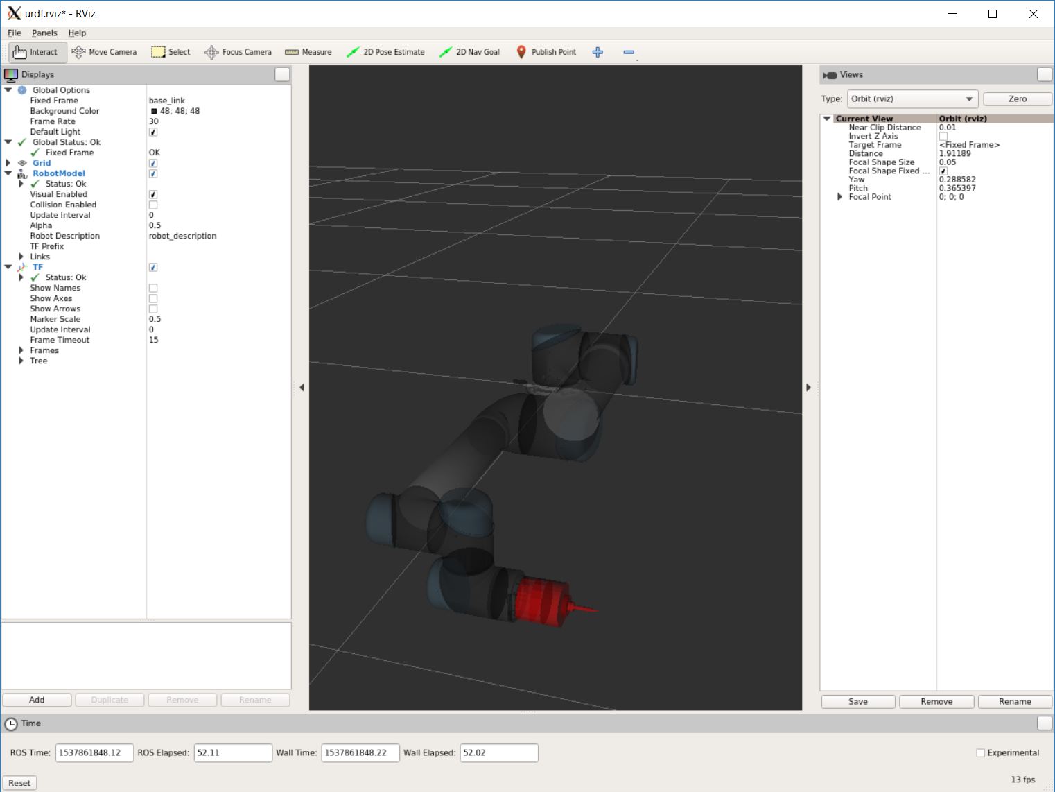
Screenshot of RViz showing the ur5 with the custom end-effector.
In RViz you can customize the display settings and save the urdf.rviz
3.7.5. Add path to search paths
For convenience, add the path to your .bashrc in order to make it available on every start of ROS:
echo 'source ~/robotic_setups/devel/setup.bash' >> ~/.bashrc