Beam
A Beam object represents a linear (straight) timber part with a rectangular cross-section - for example as a stud, rafter, beam, joist etc.
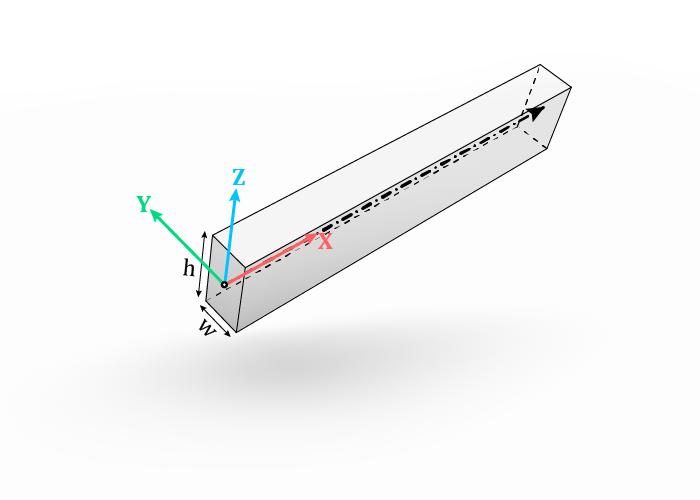
It has a local coordinate system, where the X-axis corresponds with the centerline,
Y-axis with the width of the cross-section and Z-axis with the height of the cross-section.
The origin is located at the start of the centerline.
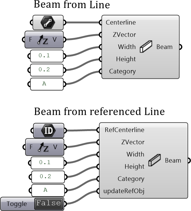
The Grasshopper plugin has two components to create beams:
BeamFromCurve - to create a beam form a Grasshopper Line or LineCurve
BeamFromCurveGuid - to create a beam from a Guid of a Line object referenced from an active Rhino document. This one is intended for a design workflow, where the input geometry (centerlines etc.) is drawn or stored in a Rhino document instead of Grasshopper.
Inputs:
Centerline : the centerline of the beam, also called the major axis.
ZVector: (optional) a vector used to define the rotation of the cross-section around the centerline. Together with the centerline it indicates the plane in which the Z-axis of the beam lies, which is to say that ZVector does not have to be perpendicular, but cannot be parallel, to the centerline. If
Noneis provided, a default direction will be used:vector [1,0,0] (X-direction in world coordinates) if centerline is vertical (parallel to Z-direction in world coordinates)
otherwise vector [0,0,1] (Z-direction in world coordinates)
Width: the smaller dimension of the cross-section (by convention).
Height: the larger dimension of the cross-section (by convention).
Category: (optional) a string as an additional attribute, used later to define joint rules in JointCategoryRule component for the AutomaticJoint tool. See also Joints.
updateRefObj: (optional, in BeamFromCurveGuid) set it to
Trueto write the new attributes to the source Line objects. See also Attributes.
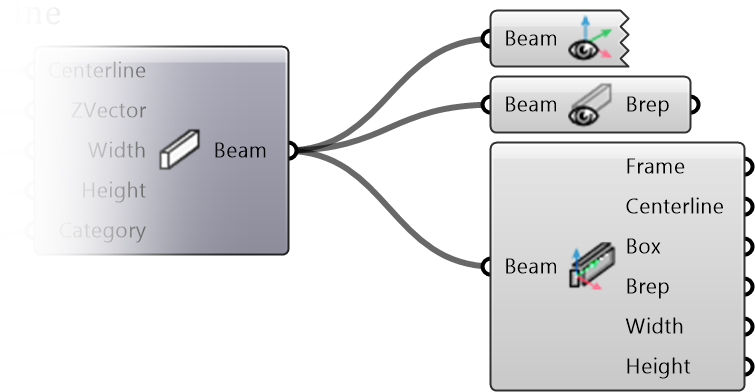
Once a Beam is created, you can preview its shape, coordinate system and extract its geometry and parameters using these components: