Assembly
Assembly component creates a structure composed of joined Beam objects. It connects the beams with joints and adds
features based on the Joints and Features inputs provided.
Geometric operations like cutting, trimming and solid boolean subtractions, which are implied by joints and features,
may be computationally expensive, and are disabled by default.
To activate it, set CreateGeometry to True.
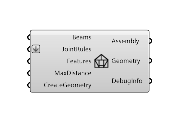
Inputs:
Beams : collection of beams.
JointsRules : collection of joint rules.
Features : collection of features definitions.
MaxDist : Max Distance Tolerance for topology detection.
CreateGeometry : If True, Beam and joint geometry is created for visualisation. Default is False.
Outputs
Assembly : Assembly object.
Geometry : Geometry of the beams and joints.
DebugInfo : Debug information object in the case of feature or joining errors.
Note
Visualisation
Assembly as such is an abstract object. To visualise the beams in the assembly, the ShowAssembly component returns a Brep geometry of the beams. See Show for the visualisation of other helpful
information such as Joint Type or Beam Index, spatially located.
For debugging, the ShowFeatureErrors component or ShowJoiningErrors component visualise the errors that occur during the assembly process. See Show.