Beam
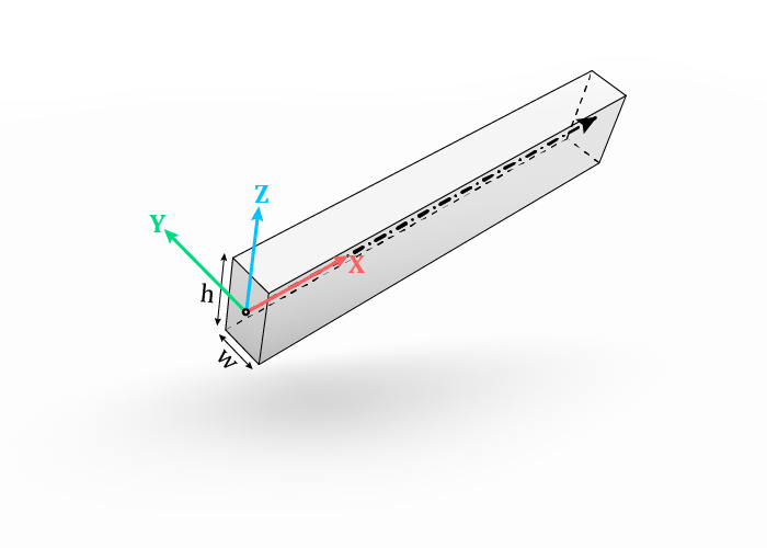
A Beam object represents a linear (straight) timber part with a rectangular cross-section - for example as a stud, rafter, beam, joist etc.
It has a local coordinate system, where the X-axis corresponds with the centerline,
Y-axis with the width of the cross-section and Z-axis with the height of the cross-section.
The origin is located at the start of the centerline.

Beams are created with the component Beam - to create a beam from a Grasshopper Line or LineCurve, or from a Guid of a Line object referenced from an active Rhino document.
The latter is intended for a design workflow, where the input geometry (centerlines, etc.) is drawn or stored in a Rhino document instead of generated within the Grasshopper environment.
Inputs:
Centerline : one or more centerline of the beam(s), also called the major axis.
ZVector: (optional) a vector used to define the rotation of the cross-section around the centerline. Together with the centerline it indicates the plane in which the Z-axis of the beam lies, which is to say that ZVector does not have to be perpendicular, but cannot be parallel, to the centerline. If
Noneis provided, a default direction will be used:vector [1,0,0] (X-direction in world coordinates) if centerline is vertical (parallel to Z-direction in world coordinates)
otherwise vector [0,0,1] (Z-direction in world coordinates)
Width: the smaller dimension of the cross-section (by convention).
Height: the larger dimension of the cross-section (by convention).
Category: (optional) a string as an additional attribute, used later to define joint rules in Direct Joint Rules component. See also Workflow.
updateRefObj: (optional) set it to
Trueto write the new attributes to the source Line objects. See also Attributes.
Outputs:
Beam : the resulting beam(s).
Blank: the corresponding blank beam. The blank represents the raw material from which the beam is cut and without Features. It is used to define the stock size for the beam.
Once a Beam is created, it can be used as an input for the Assembly component or the following components:
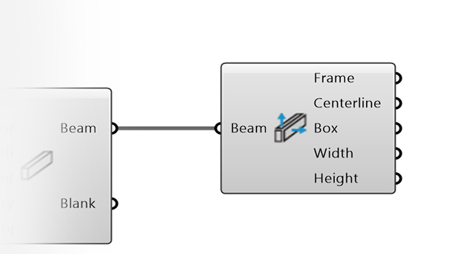
DecomposeBeam : extracts the frame, centreline, box, width and height from a beam.
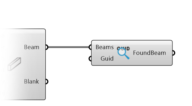
FindBeamByRhinoGeometry : finds the beam corresponding to a referenced Rhino curve or line.