Rhino Basics
Introduction
Training guide for Rhino 6 or later.
Rhinoceros, is a 3D CAD modeling software package that enables you to accurately model your designs ready for rendering, animation, drafting, engineering, analysis, and manufacturing. Rhino is a free-form NURBS surface modeler.
![]()
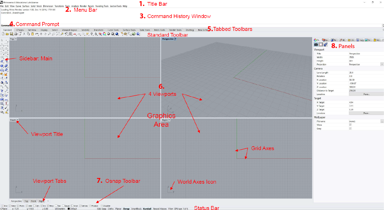
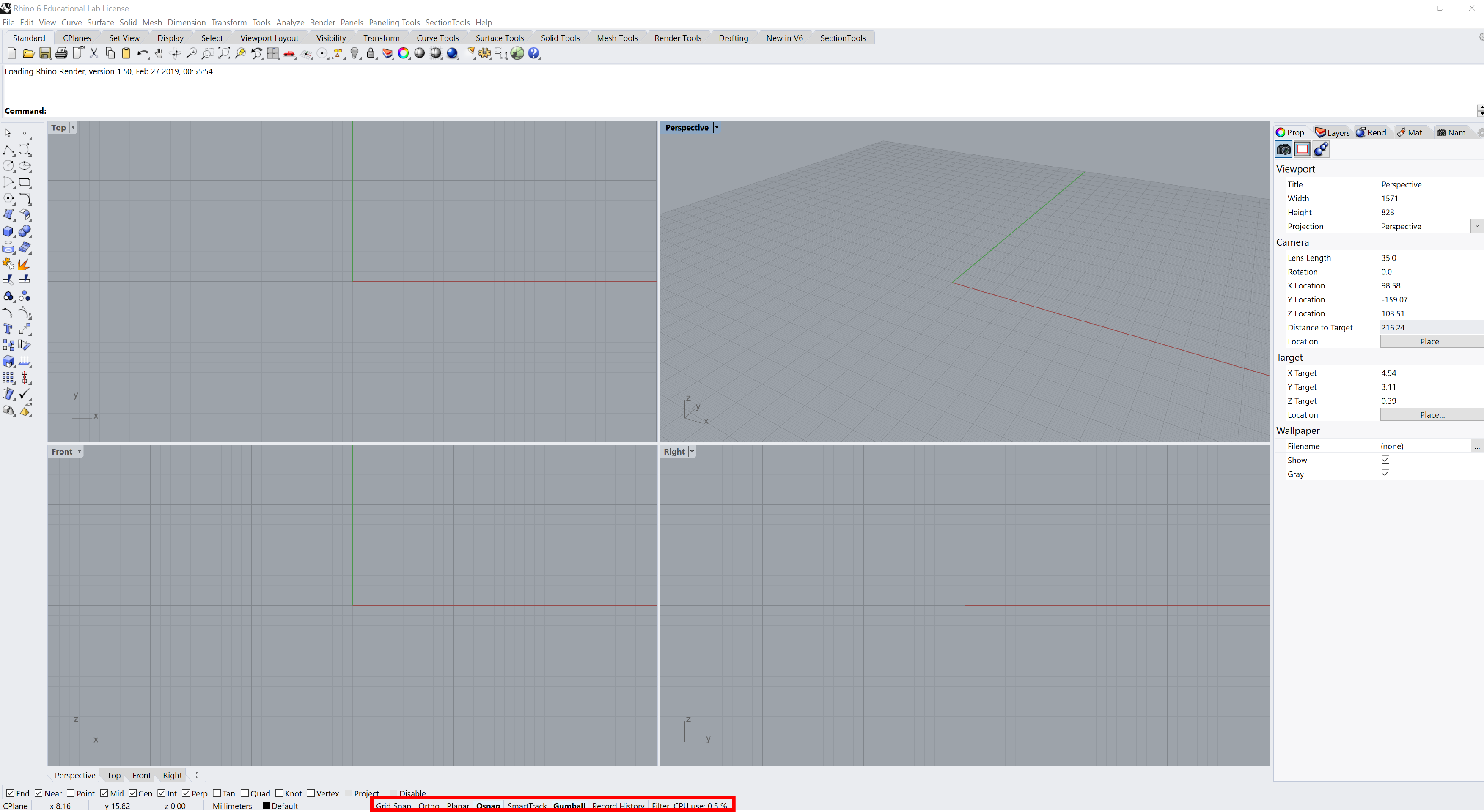
Interface
Rhino divides its screen into different areas:
| Title | Description |
|---|---|
| 1. Window / Title bar | Displays the current model’s file name and file size. |
| 2. Menu bar | Groups Rhino commands by function. |
| 3. Command history window | Displays the previous commands. |
| 4. Command prompt | Use the Command line to type commands, click command options, type coordinates, type distances, angles, or radii, type shortcuts, and view command prompts. |
| 5. Tabbed Toolbar | Contain graphical icons for initiating commands. |
| 6. Viewports | Displays the Rhino working environment including object display, viewport title, background, construction plane grid, world axis icon. |
| 7. Osnap Toolbar | Contains persistent object snap toggles. |
| 8. Panels | Many Rhino controls are contained in tabbed panels. The panels are docked to the right side of the Rhino screen by default. |
Viewport navigation
| Action | Key |
|---|---|
| orbit | Right button |
| pan | Right button + shift |
| zoom | Scroll |
| select | Left button |
| select exclusive | Left button drag right |
| select inclusive | Left button drag left |
| force orthogonal | Press + hold shift |
| lock direction | Press tab |
Helpers
Modeling Aids
| Helper | Description |
|---|---|
| Grid Snap | Snap to grid intersections |
| Ortho | Constrains the marker movement to the points at a specified angle from the last point created |
| Planar | This helps you model planar objects by constraining the input to be on a plane parallel to the construction plane |
| Osnap | Object snaps constrain the marker to an exact location on an object |
| SmartTrack | Temporary reference lines and points that are drawn in the Rhino viewport |
| Gumball | Display widget, on a selected object, facilitating move, scale, and rotate transformations |
| Record History | Records history and updates history-aware objects |
| Filter | Restricts any selection mode to specified object types |
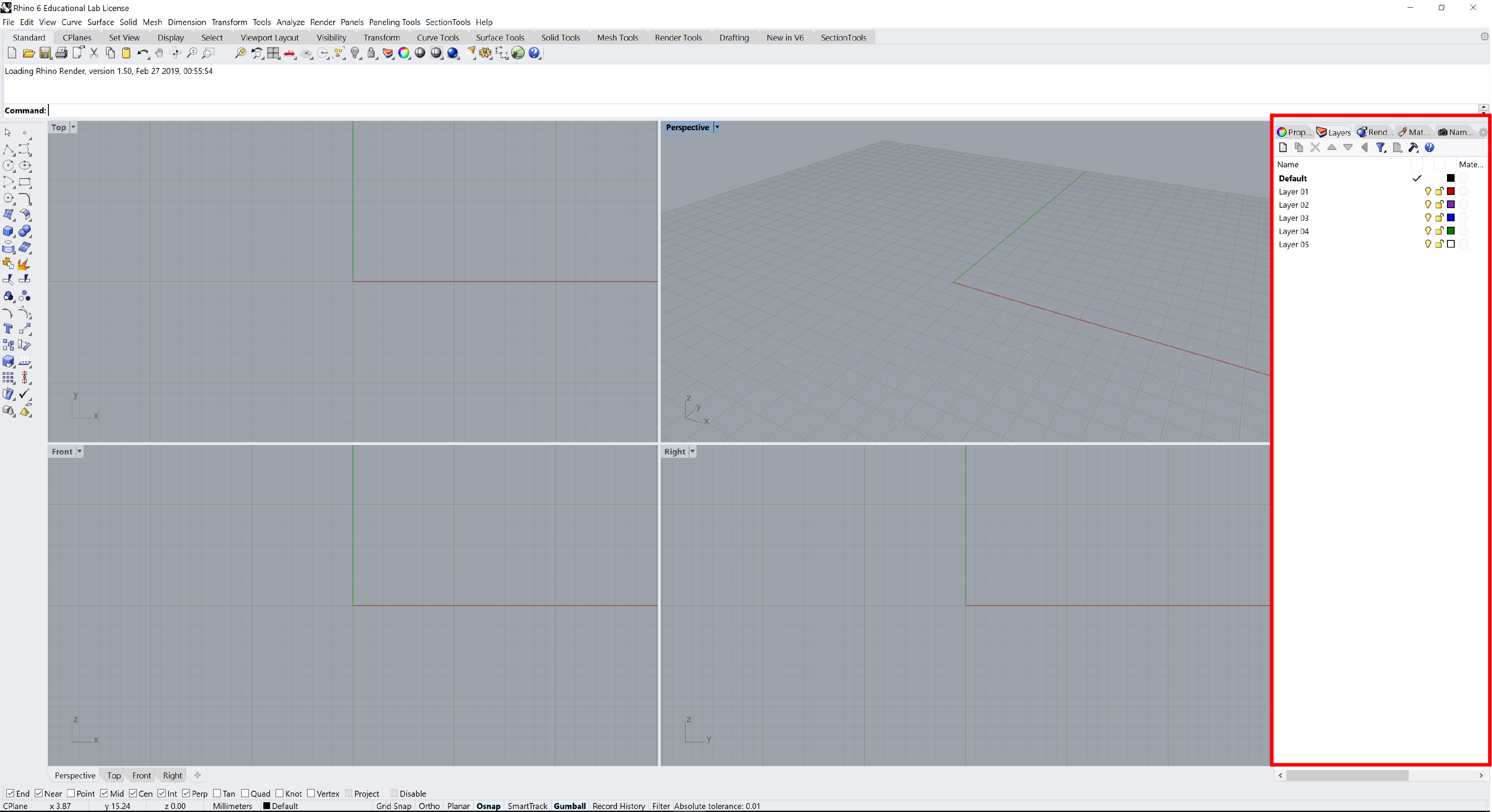
Layers
By creating objects on different layers, you can edit and view related portions of a model separately or as a composite.
Geometry editing
Operations
| Commands | Description |
|---|---|
| Move | Move objects without changing orientation or size. (Transform/ Move) |
| Copy | Duplicates selected objects and places them in a new location. (Transform/ Copy) |
| Rotate | Move objects in a circular motion around a base point. (Transform/ Rotate) |
| Mirror | Creates a copy of the objects flipped over a specified axis on the construction plane. (Transform/ Mirror) |
| Group | Grouping objects allows all members of the group to be selected as one. (Edit/Groups/ Group) |
| Trim | Cuts and deletes portions of an object to make it end precisely at its intersection with another object. (Edit/ Trim) |
| Split | Divides objects into parts using other objects as cutters. (Edit/ Split) |
| Extend | Lengthens an object to make it end precisely at its intersection with another object or you can lengthen an object when there is no intersection. (Curve/ Extend Curve/ Extend Curve) |
| Offset curve | Creates an object parallel or concentric to another object. (Curve/ Offset/ Offset Curve) |
| Offset surface | Creates an object parallel or concentric to another object. (Surface/ Offset Surface) |
| Array | Make multiple copies of selected objects. (Transform/ Array) |
| Loft | Fits a surface through selected profile curves that define the surface shape. (Surface/ Loft) |
| Fillet | Connects two lines, arcs, circles, or curves extending or trimming them to touch or to join with a circular arc. (Curve/ Fillet Curve) |
| Chamfer | Connects two curves by extending or trimming them to intersect or to join with a beveled line. (Curve/ Chamfer Curve) |
| Etc… |
Point editing
You can display the control points or the edit points of an object so that you can adjust the shape of an object, rather than manipulating the whole object at once.
(Edit/Control Points/ Control Points ON)
F10
Control points determine the shape of a curve. Typically, each point of the curve is computed by taking a weighted sum of a number of control points.
Adding more control points allows better approximation to a given curve, although only a certain class of curves can be represented exactly with a finite number of control points.
Control points do not have to be on the curve or surface.
Curve Control Points
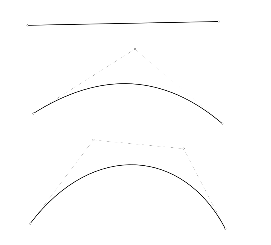 Curve Degree 1:Line , Curve Degree 2: Parabola, Arc, Circle and Curve Degree 3: Curve
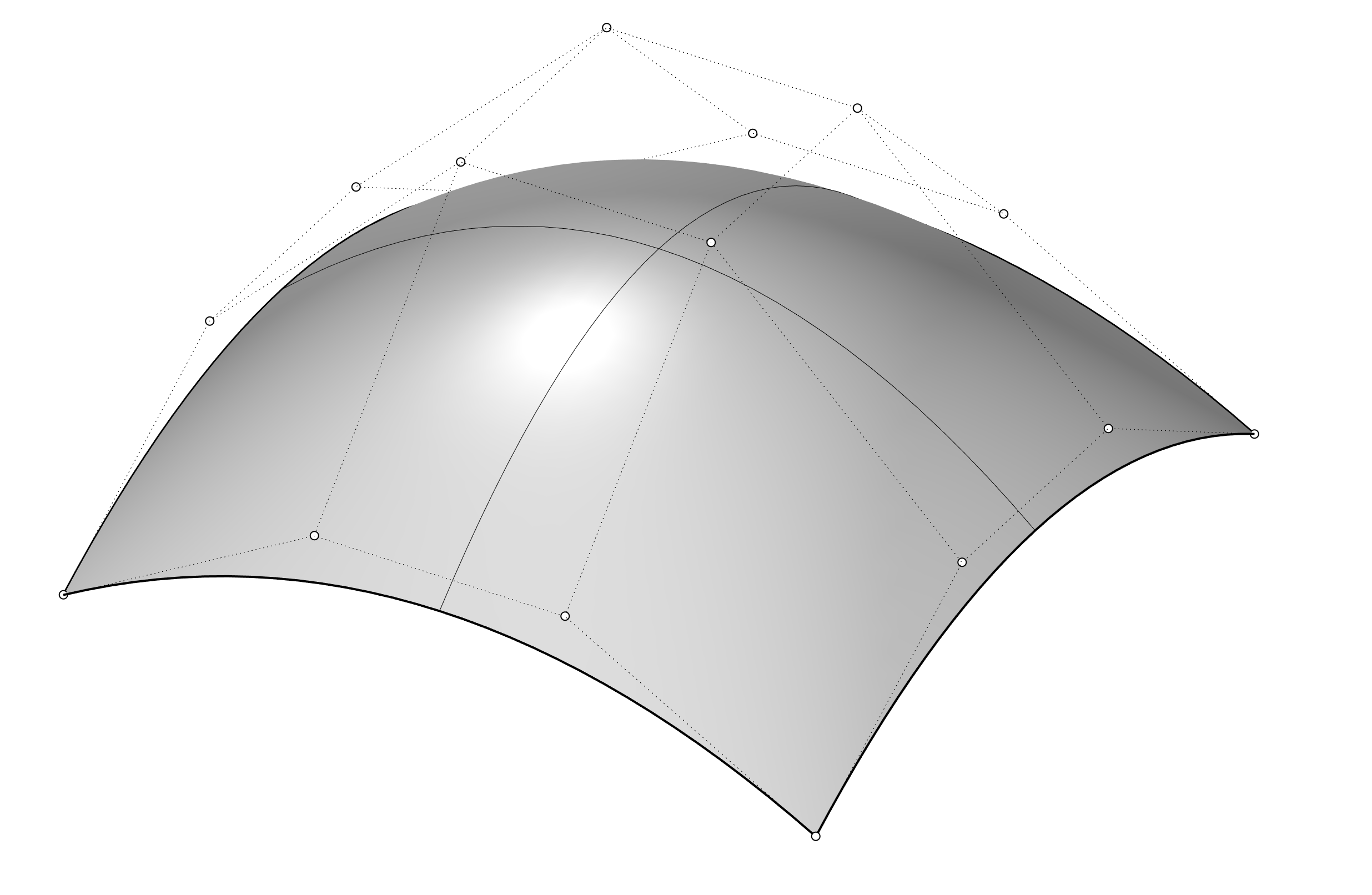
Surface Control Points
(more info: http://docs.mcneel.com/)
Edit points
You can use point editing on meshes, curves, and surfaces, but not on polysurfaces or solids. Rhino’s curves are represented internally with non-uniform rational B-splines(NURBS). Three things determine the shape of a NURBS curve:
- A list of points called control points
- Degree
- A list of numbers called knots If you change any of these things, it changes the shape of the curve.
Edit points are always on the curve.
Knots
Part of the information needed to define a NURBS curve is a list of numbers called a knot vector and the values of the numbers in this list are called knots.
Knots are parameters (that is, numbers, not points).
(info: http://docs.mcneel.com/)
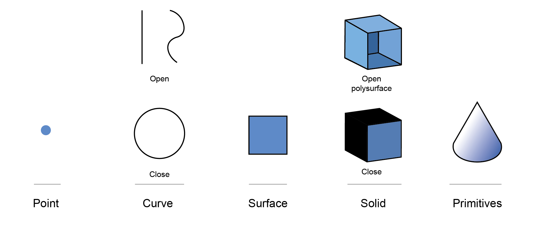
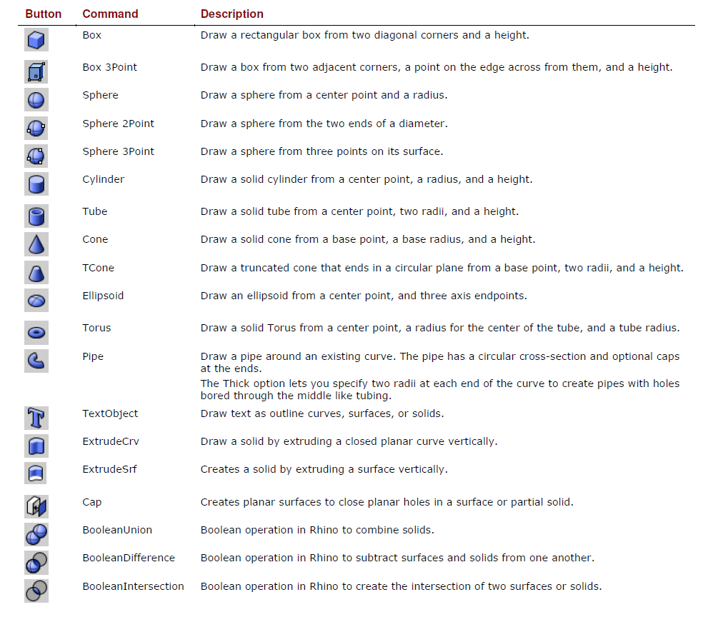
Solid Modelling
Solids are closed surfaces or polysurfaces that enclose a volume.
Some of the solid primitives are closed single-surfaces, others are polysurfaces.
Polysurface objects are deformable by using the deformation commands.
You can also extract surfaces and deform the surfaces with control point editing.
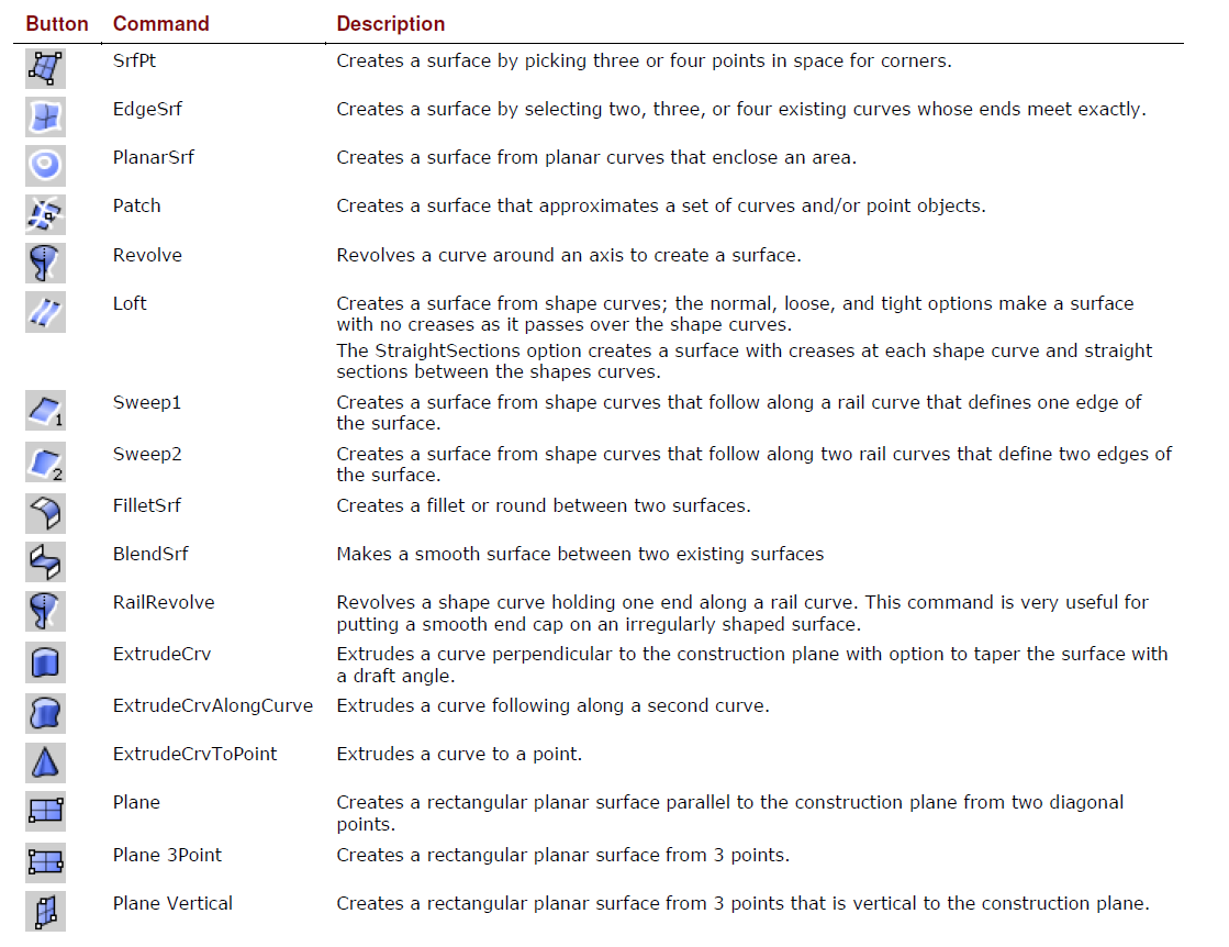
Surfaces
Surfaces are bounded by curves called edges.
Surfaces have an area, their shape can be changed by moving control points, and they can be meshed.