First steps into UR control
UR Basics
- Introduction
- Network
- Tools
- Inputs and Outputs
- Relative and Absolute
- Speed
- Precision
- Commands
- Rotations
- Motion and rotation
- Moving between targets
- Axes
- Tool definition
Introduction
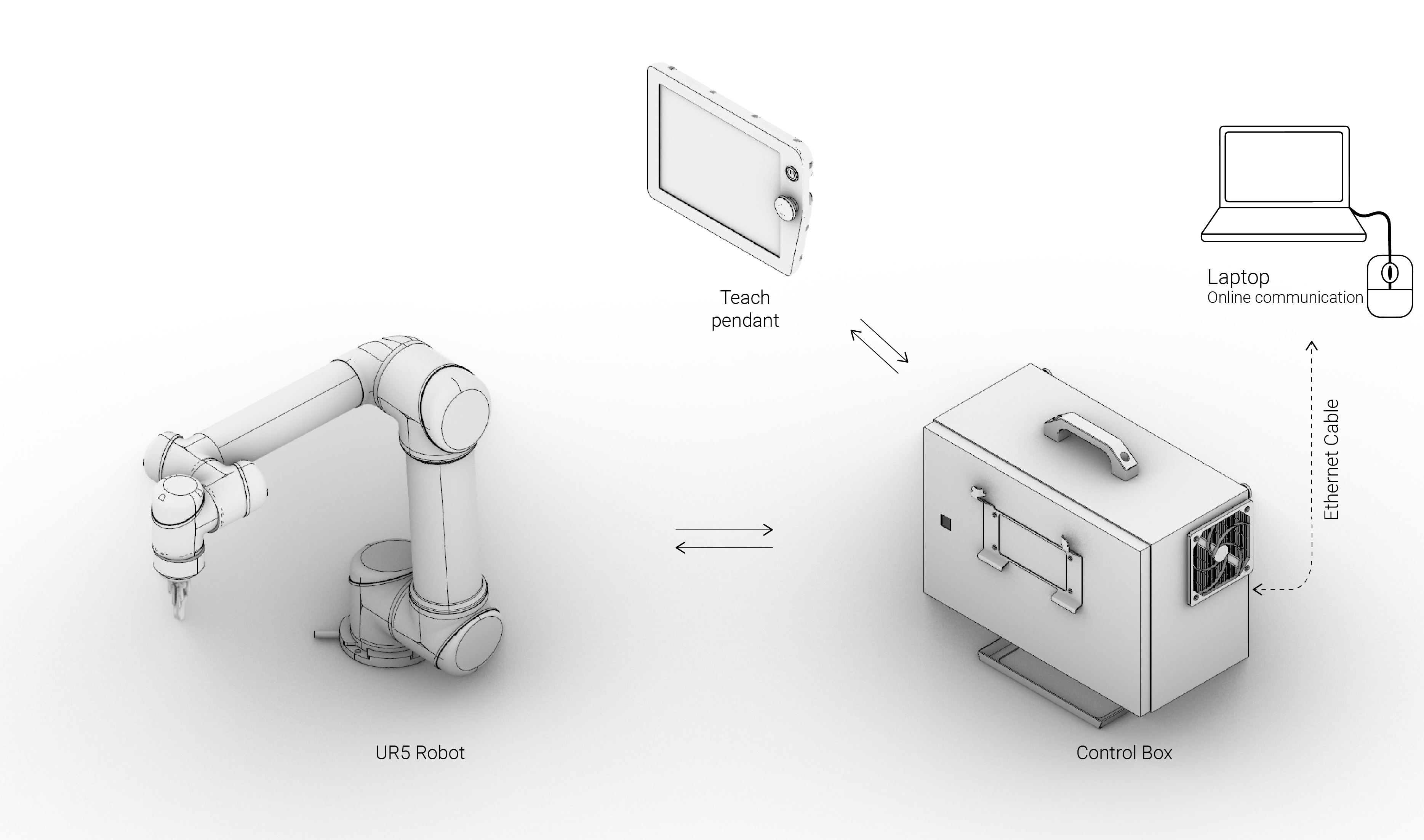
Elements of the robot
- Robotic arm
- Controller box
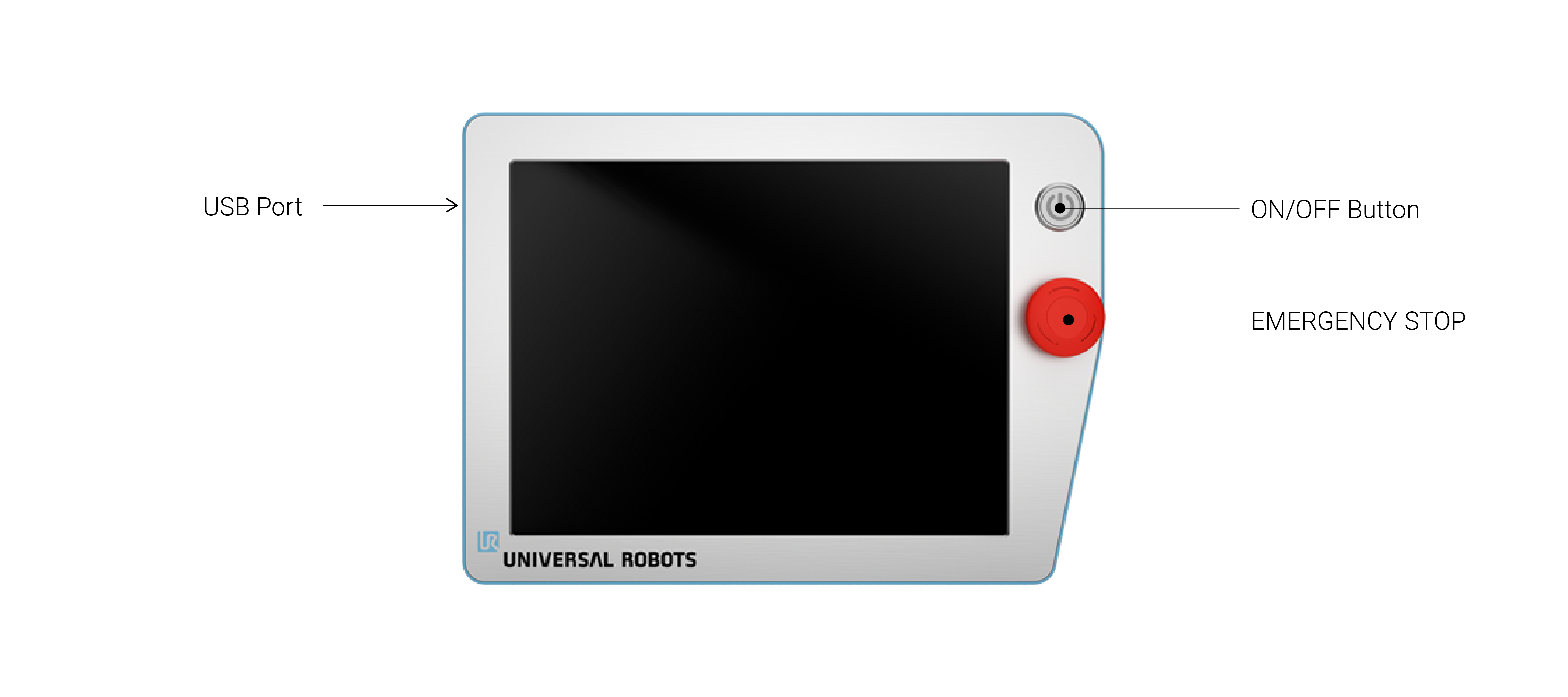
- Teach pendant (Interface)
- USB Port
- ON/OFF Button
- EMERGENCY STOP
Teach pendant
Initialization
- Turn ON Robot
- Release motors
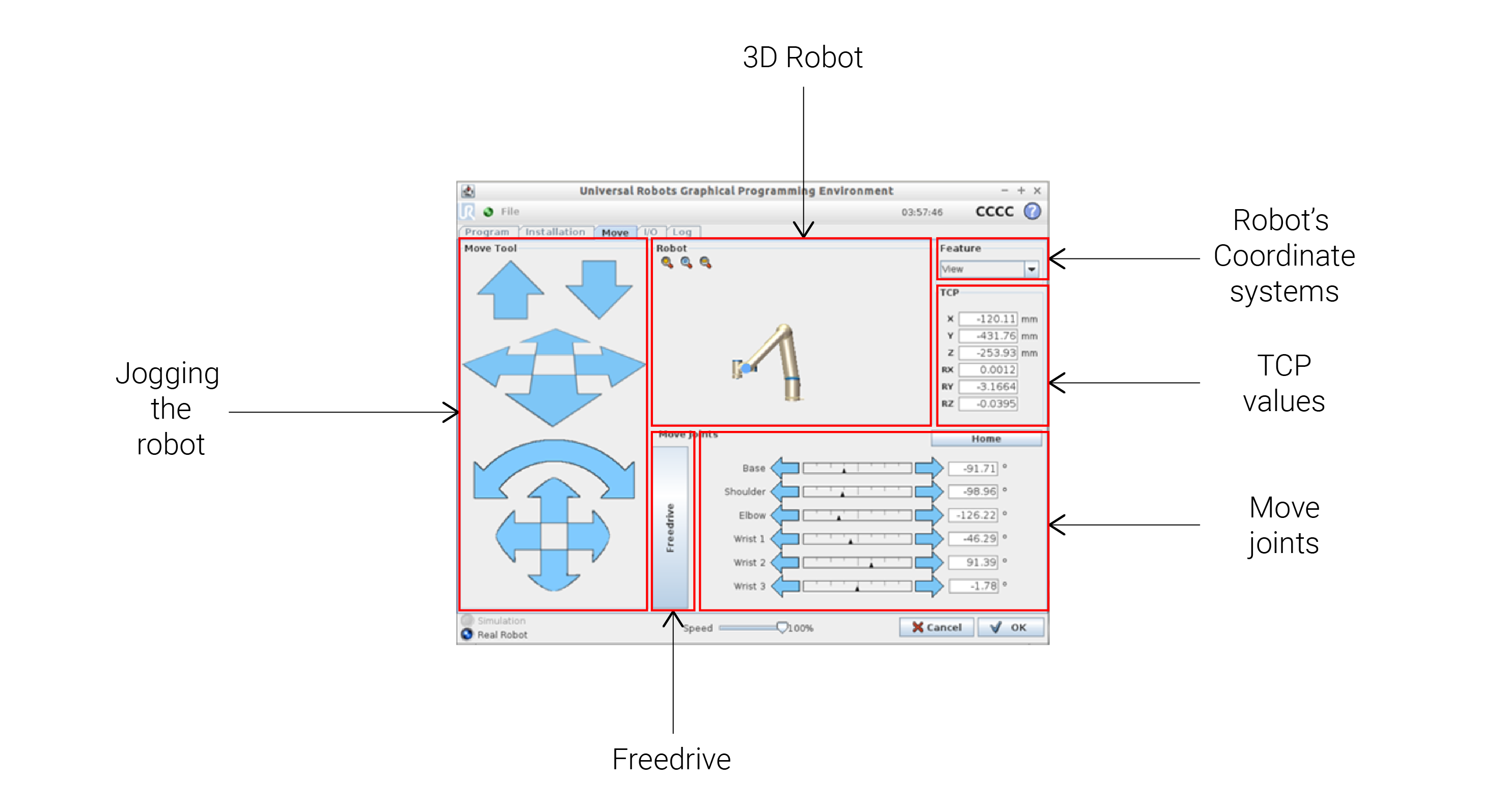
Jog robot
Different parts:
- Jogging the robot
- Robot - 3D representation
- TCP values
- Joints angular values
- HOME POSITION (0, -90, -90, -90, 90, 90)
- Free-drive + Backside button
Network
Configuration
- Connection
- Ethernet cable
- Wireless (not recommended)
- Network
- DHCP (non-static)
- Static Address
- IP Address: 192.168.0.xx
- Subnet mask: 255.255.255.0
- Connection Check: cmd promt (Win)
- ping
- ipconfig
Tools
- End-effector name
- Sand extruder
- Gripper
- Pencil
- Filament extruder
- etc…
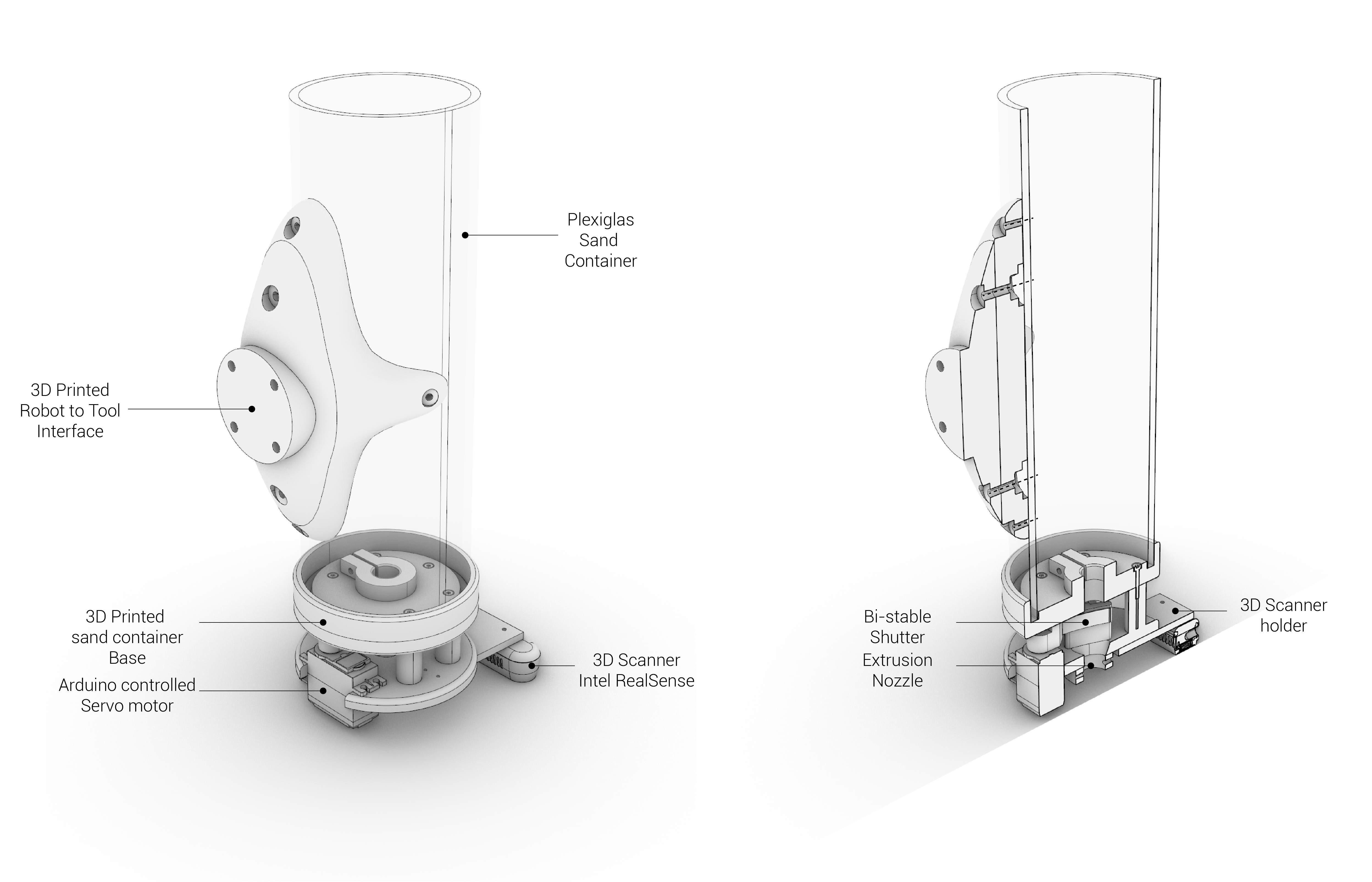
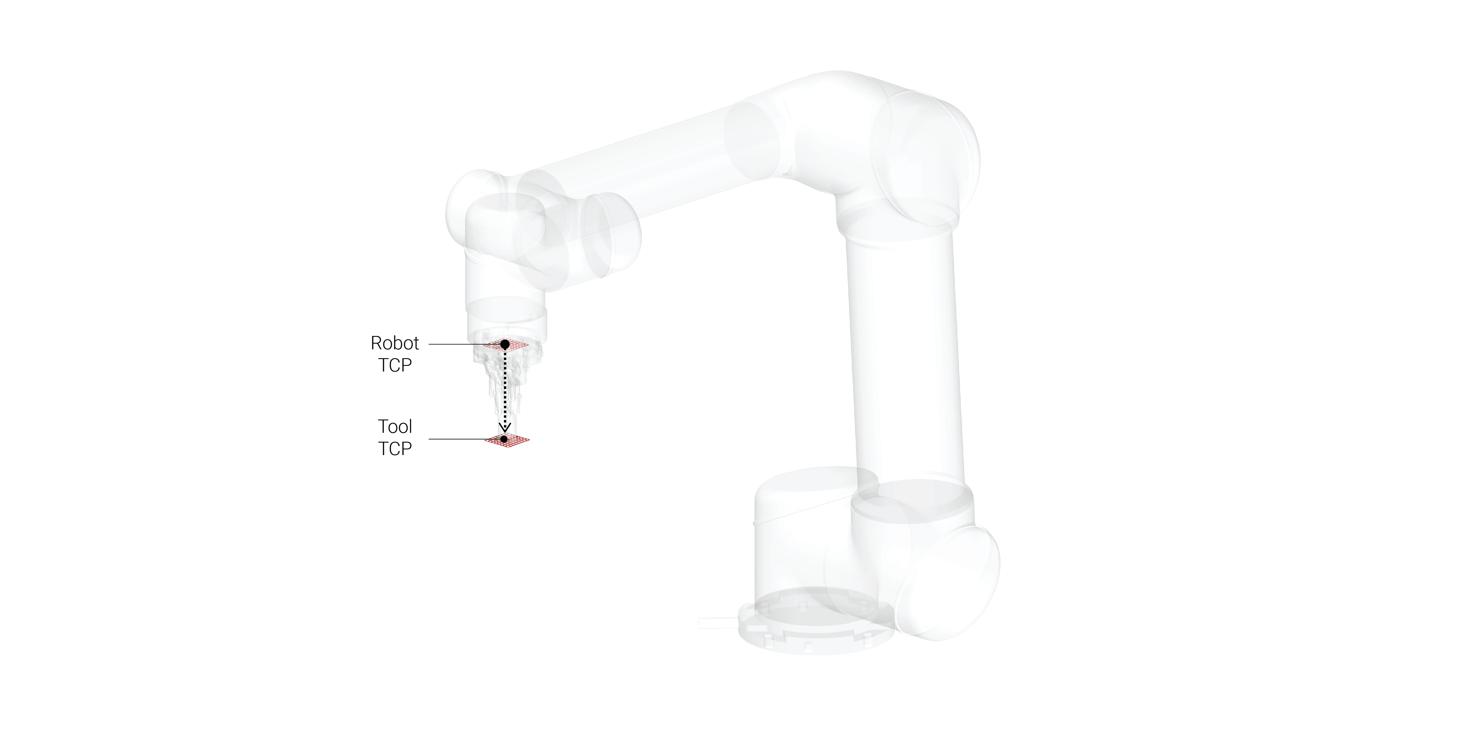
- TCP (Tool Center Point)
- Adjusted for every tool

- Weight adjustment
- Tool specific electronics
- Arduino
- Servo motor
- I/O
- From flex pendant
- From code (commands)
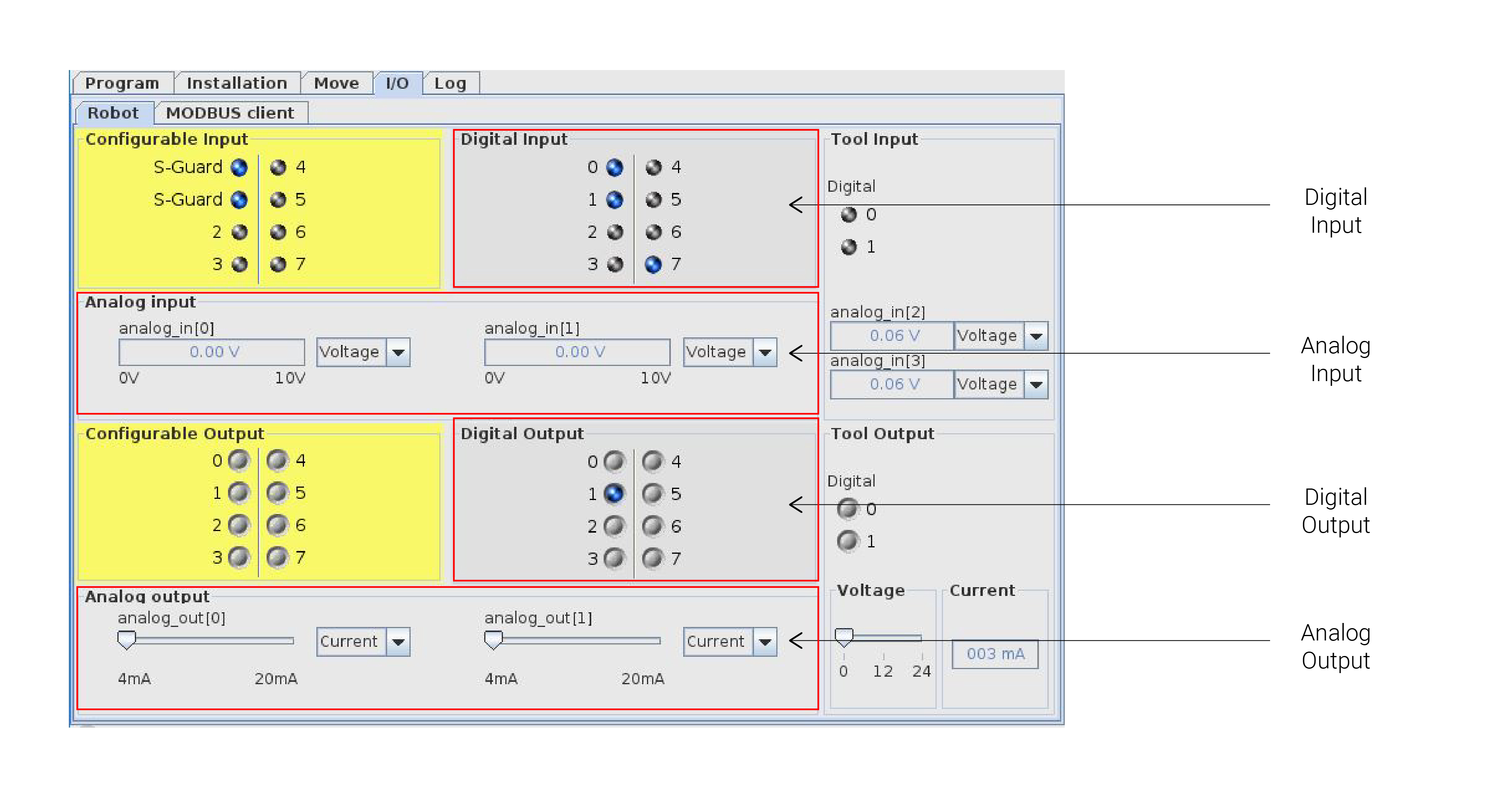
Inputs and Outputs
- Robot have many pins for Inputs and Outputs:
- Write (Output)
- Digital (0,1)
- Analog (values)
- Read (Input)
- Digital (0,1)
- Analog (values)
- Write (Output)
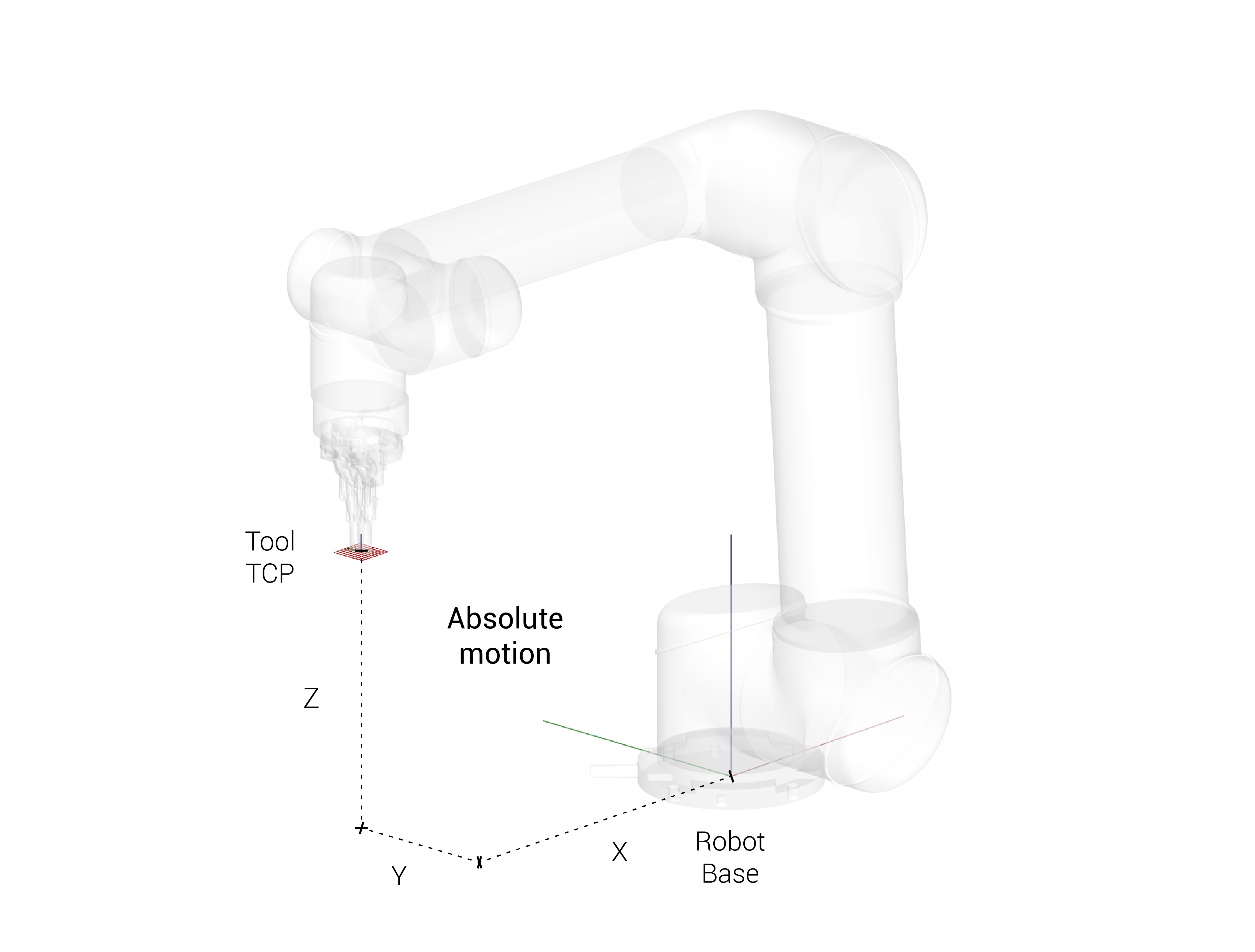
Relative and Absolute
Absolute position
Move anywhere in space based on the coordinate system of the robot
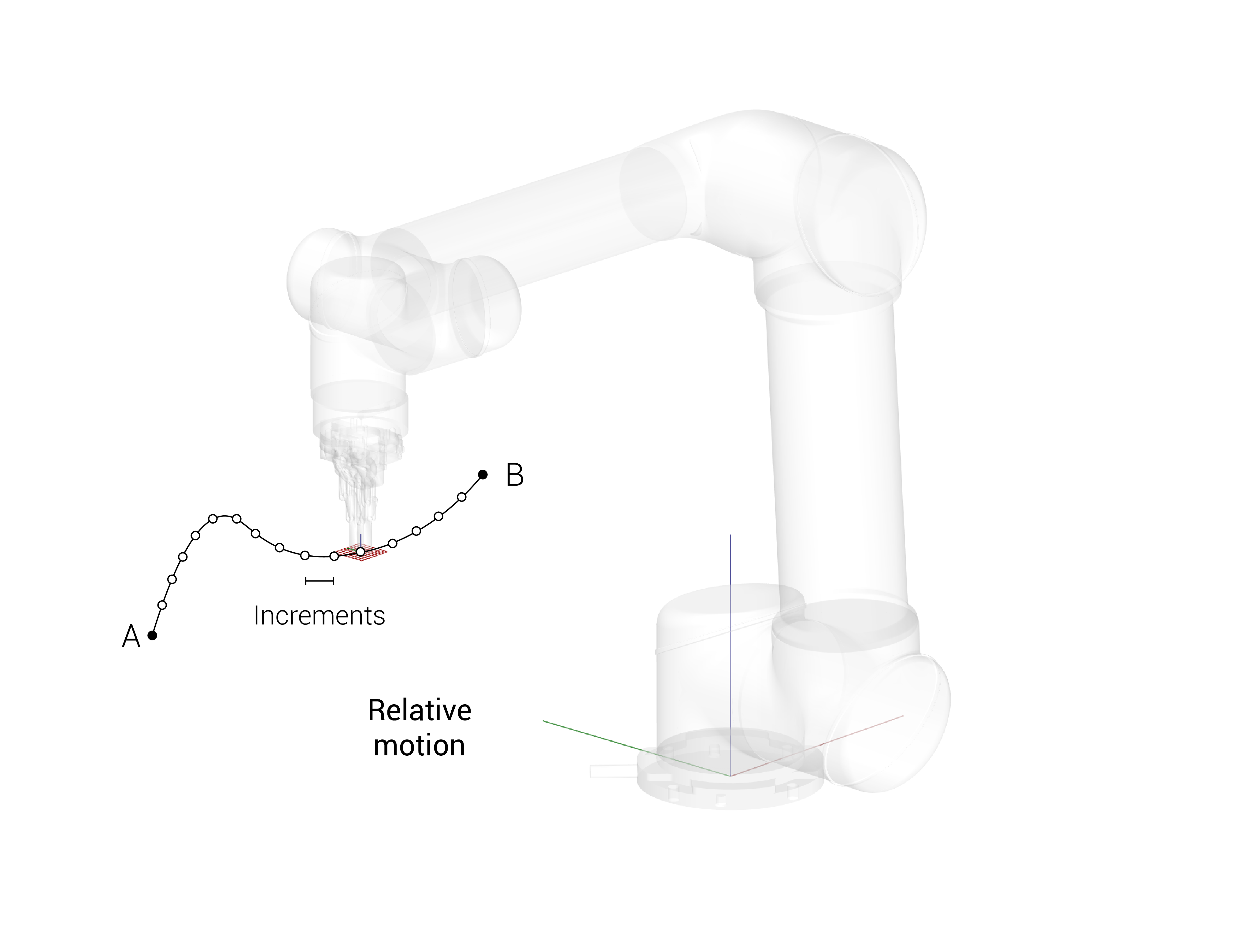
Relative position
Increments from wherever the robot was before in small steps
Speed
Absolute speed
Base speed
Relative speed
Incremented speed
Units
Millimeters per second (mm/s)
Precision
The robot never reaches the target that you have sent
radius = 0
radius > 0 (Blend radius in between trajectories)
Commands
List of command sequence (individual commands)
Block of actions
![]() Check: Robot reach
Check: Robot reach
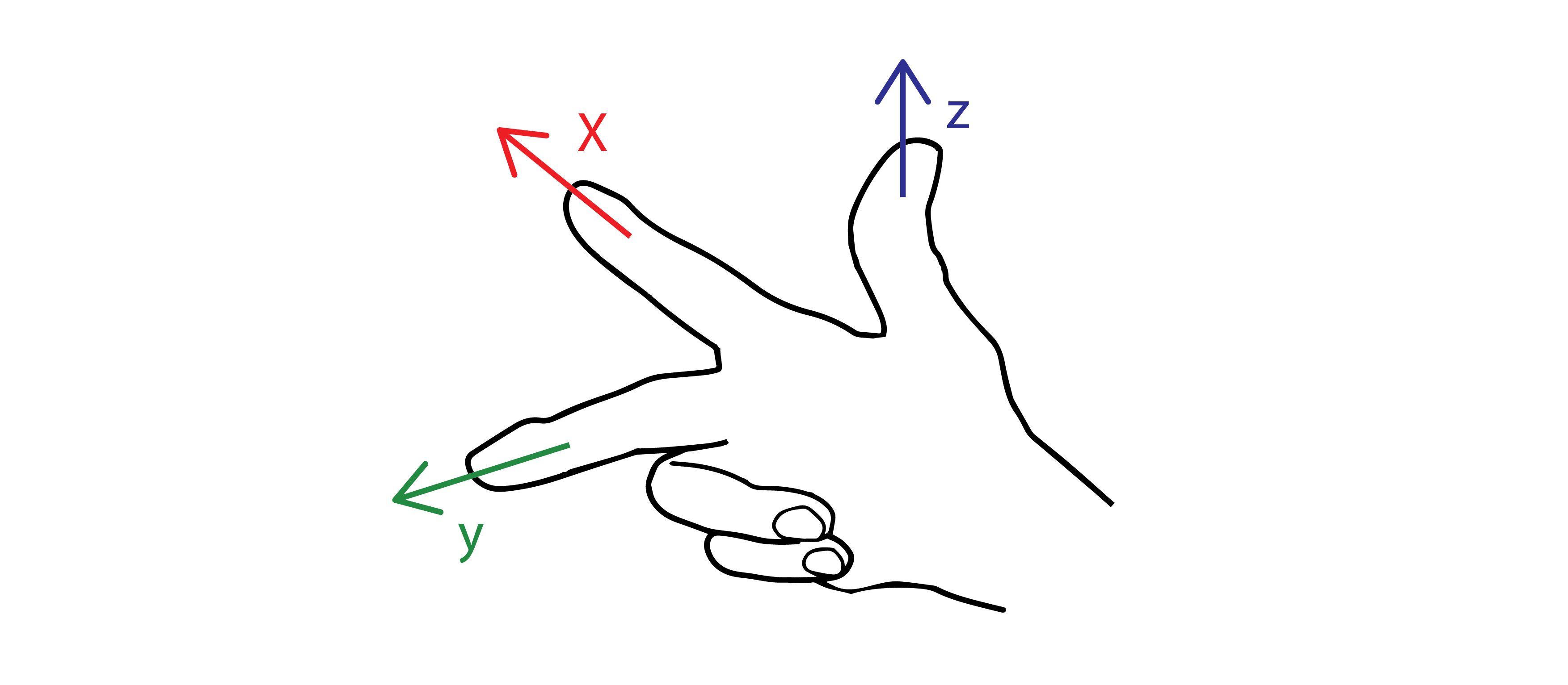
Rotations
Right hand rule
Absolute
From Base
Relative
From TPC
X (1,0,0) + angle
Y (0,1,0) + angle
Z (0,0,1) + angle
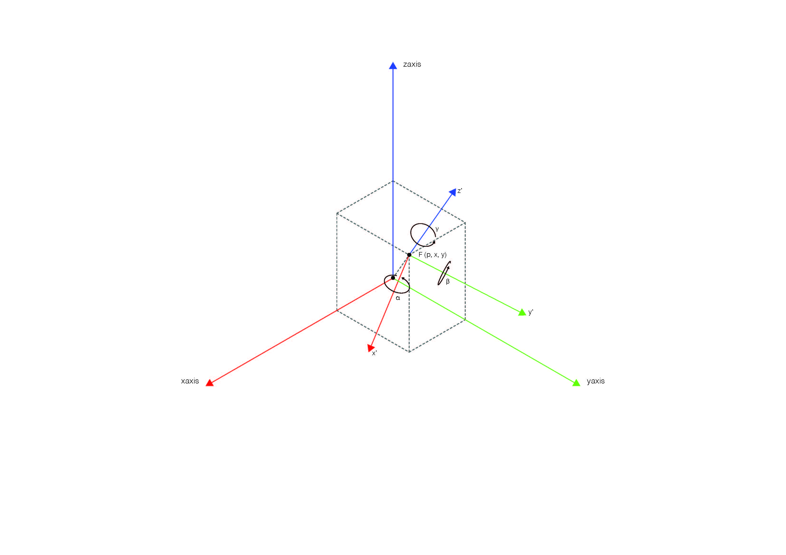
Motion and rotation
Changes position and orientation
pose = p[x,y,z,rx,ry,rz]
Example:
Position in base frame of:
- x = 200 mm
- y = 300 mm
- z = 500 mm
- rx = 0
- ry = 0
- rz = 180 deg
pose = p[0.2,0.3,0.5,0,0,3.14]

Frame transformation

Moving between targets
moveL
Move to position (linear in tool-space):
movel(pose, a=1.2, v=0.25, t=0, r=0)
Parameters
- pose: target pose (pose can also be specified as joint positions, then forward kinematics is used to calculate the corresponding pose)
- a: tool acceleration [m/s^2]
- v: tool speed [m/s]
- t: time [S]
- r: blend radius [m]
Example command:
movel(pose, a=1.2, v=0.25, t=0, r=0)
Example Parameters:
- pose = p[0.2,0.3,0.5,0,0,3.14] → position in base frame of x = 200 mm, y = 300 mm, z = 500 mm, rx = 0, ry = 0, rz = 180 deg
- a = 1.2 → acceleration of 1.2 m/s^2
- v = 0.25 → velocity of 250 mm/s
- t = 0 → the time (seconds) to make the move is not specified. If it were specified the command would ignore the a and v values.
- r = 0 → the blend radius is zero meters
moveJ
Move to position (linear in joint-space). The t parameter can be used to set the time for this move. Time setting has priority over speed and acceleration settings.
movej(q, a=1.4, v=1.05, t=0, r=0)
Parameters
- q: joint positions (q can also be specified as a pose, then inverse kinematics is used to calculate the corresponding joint positions)
- a: joint acceleration of leading axis [rad/s^2]
- v: joint speed of leading axis [rad/s] t: time [S]
- r: blend radius [m] If a blend radius is set, the robot arm trajectory will be modified to avoid the robot stopping at the point. However, if the blend region of this move overlaps with the blend radius of previous or following waypoints, this move will be skipped, and an ’Overlapping Blends’ warning message will be generated.
Example command:
movej([0,1.57,-1.57,3.14,-1.57,1.57], a=1.4, v=1.05, t=0, r=0)
Example Parameters:
- q = [0,1.57,-1.57,3.14,-1.57,1.57] → base is at 0 deg rotation, shoulder is at 90 deg rotation, elbow is at -90 deg rotation, wrist 1 is at 180 deg rotation, wrist 2 is at -90 deg rotation, wrist 3 is at 90 deg rotation. Note: joint positions (q can also be specified as a pose, then inverse kinematics is used to calculate the corresponding joint positions)
- a = 1.4 → acceleration is 1.4 rad/s/s
- v = 1.05 → velocity is 1.05 rad/s
- t = 0 → the time (seconds) to make move is not specified. If it were specified the command would ignore the a and v values.
- r = 0 → the blend radius is zero meters.
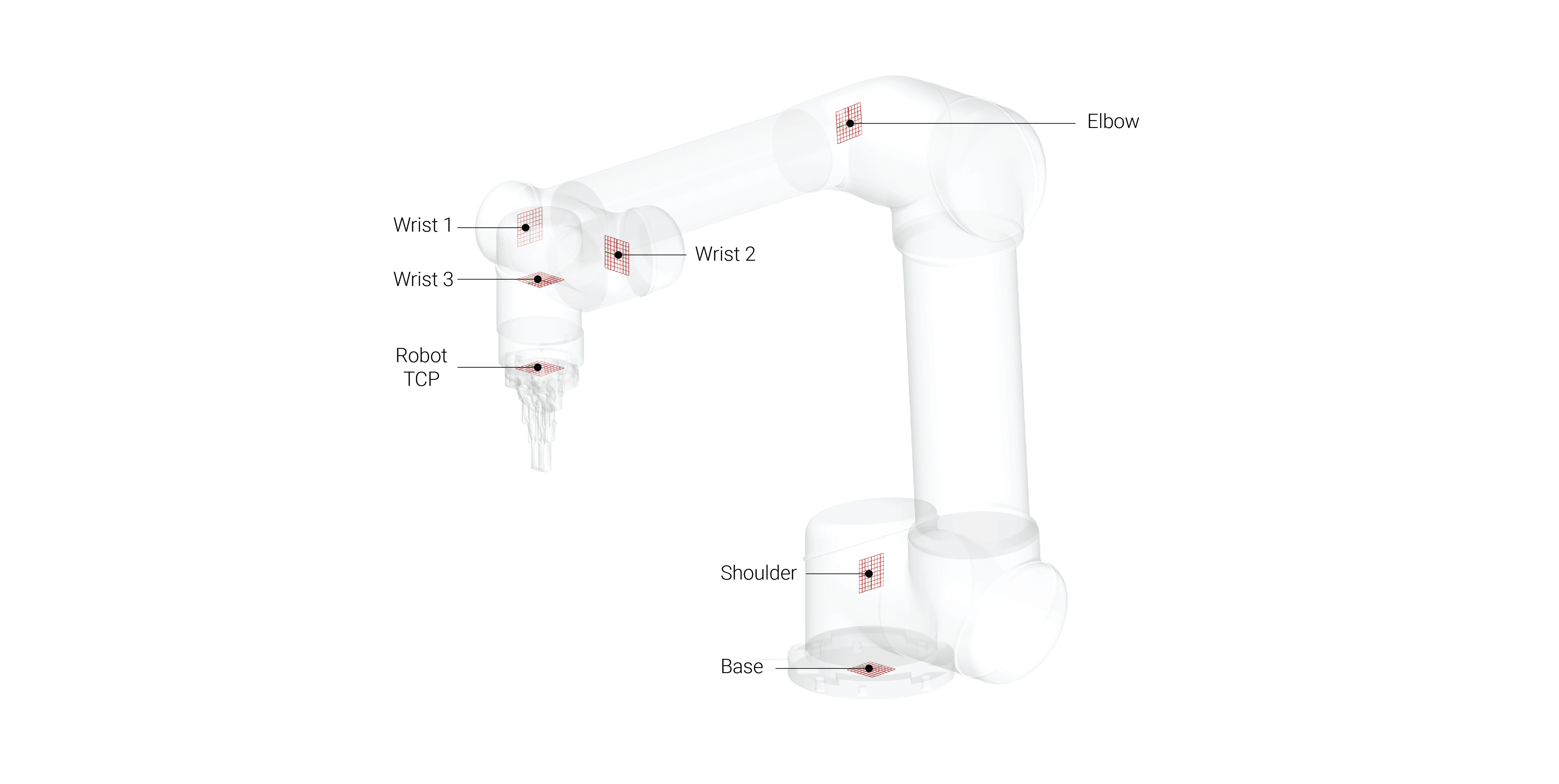
Axes
6 axes
- Base
- Shoulder
- Elbow
- Wrist 1
- Wrist 2
- Wrist 3
Kinematics
- Inverse
- Defined by pose coordinates
- Forward
- Defined angle value (joint position)
- Absolute Axes (0, -90, -90, -90, 90, 90)
- Relative Axes (10, 0, 0, 0, 0, 0) - Incremental