Creating a URDF of the UR10 on two linear axes
Export meshes
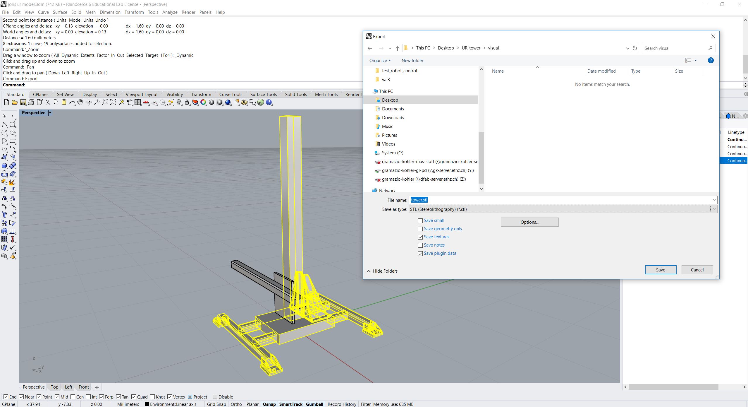
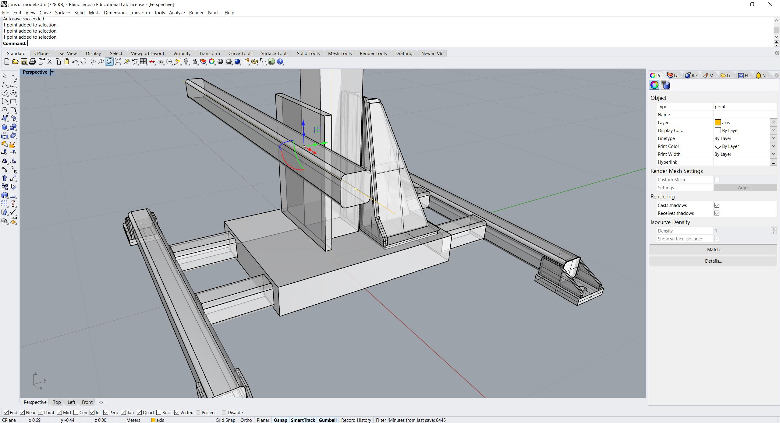
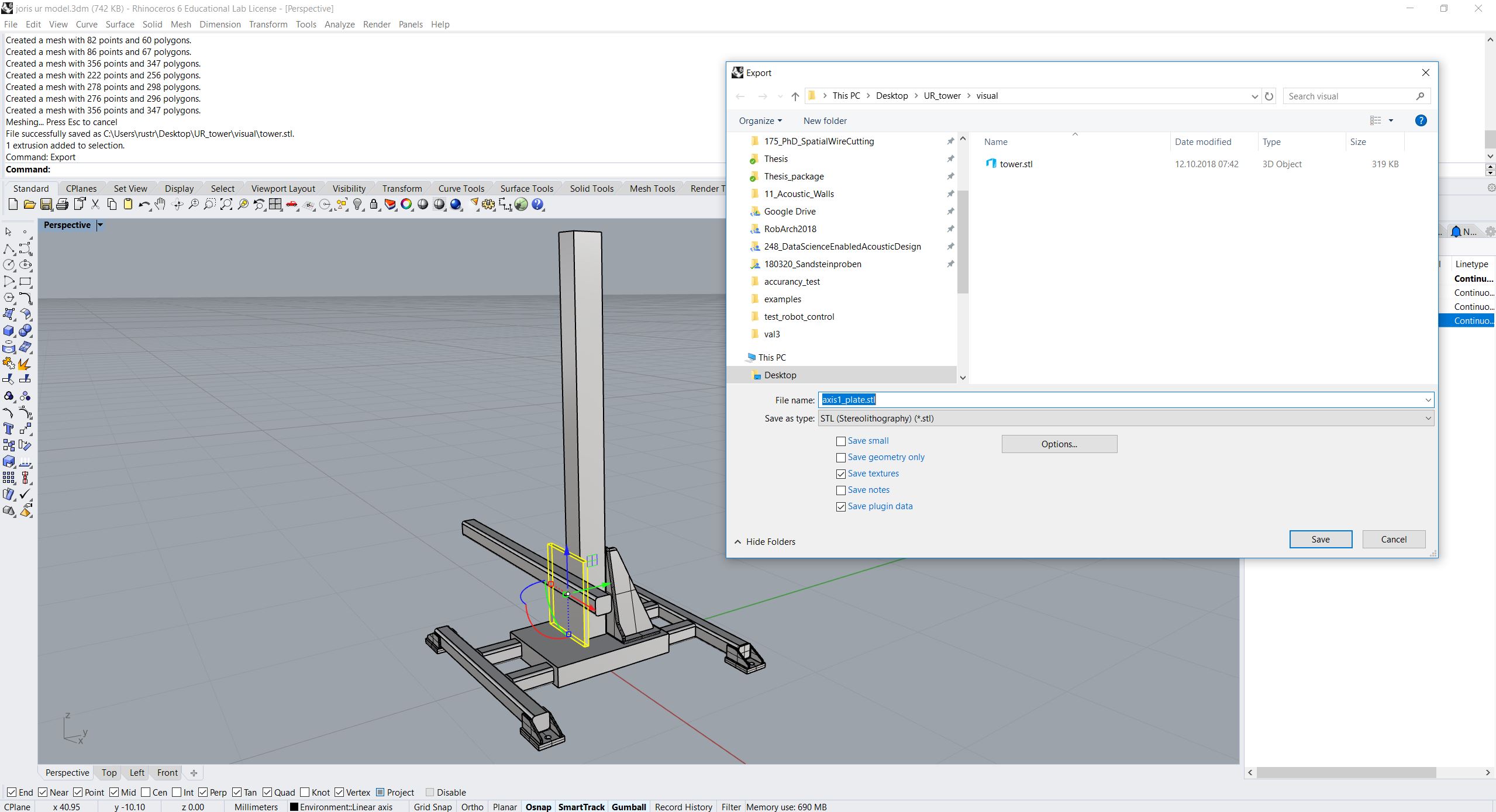
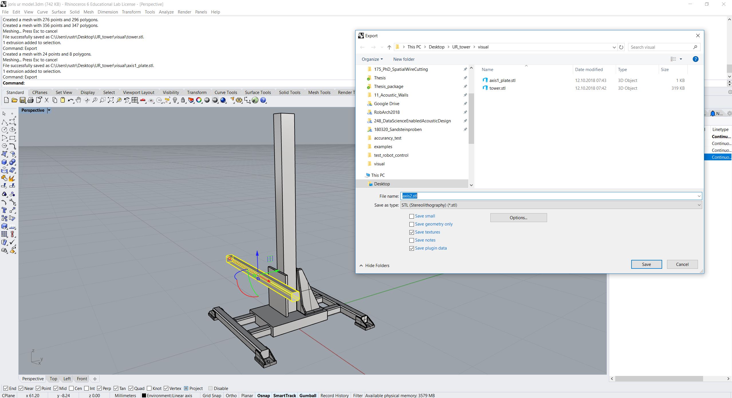
Before exporting, please move the elements of the tower’s axes such that they are positioned in their zero-positions and make sure that the model is defined in meters.
Define the axes with lines and mark the initial joint positions with a point.
Then export both visual and collision meshes: For the moveable meshes choose “Export with origin” and select the respective point you just defined before. The export format must be ROS-friendly, like .stl or .obj (see below). (Here we use the same visual and collision meshes.)

Prepare your catkin workspace
Open your command prompt and go to your robotic setups src folder:
cd ~/robotic_setups/src
Make a package with your new setup ur10_tower and go to the newly created folder:
catkin_create_pkg ur10_tower
cd ur10_tower
This will create a ur10_tower folder which contains a package.xml and a
CMakeLists.txt. Then open package.xml and add the following lines after
the line <buildtool_depend>catkin</buildtool_depend>.
<buildtool_depend>catkin</buildtool_depend>
<test_depend>roslaunch</test_depend>
<build_export_depend>joint_state_publisher</build_export_depend>
<build_export_depend>robot_state_publisher</build_export_depend>
<build_export_depend>rviz</build_export_depend>
<build_export_depend>xacro</build_export_depend>
<exec_depend>joint_state_publisher</exec_depend>
<exec_depend>robot_state_publisher</exec_depend>
<exec_depend>rviz</exec_depend>
<exec_depend>xacro</exec_depend>
Optionally, modify email and licence, version tags.
Then create 4(+2) folders: launch, rviz, urdf and meshes (with visual and collision folders):
mkdir ~/robotic_setups/src/{launch,rviz,urdf,meshes,meshes/visual,meshes/collision}
Copy your meshes into meshes/visual and meshes/collision.
Create xacros and generate urdf
tower.xacro
Go to the urdf folder and create a xacro file for the tower:
cd ~/robotic_setups/src/urdf
pico tower.xacro
Paste the following into the file:
<?xml version="1.0" encoding="utf-8"?>
    <robot xmlns:xacro="https://ros.org/wiki/xacro">
        <xacro:macro name="tower" params="prefix">
            <link name="${prefix}tower">
                <visual>
                    <geometry>
                        <mesh filename="package://ur10_tower/meshes/visual/tower.stl"/>
                    </geometry>
                    <material name="">
                        <color rgba="1.0 1.0 1.0 1.0"/>
                    </material>
                </visual>
                <collision>
                    <geometry>
                        <mesh filename="package://ur10_tower/meshes/collision/tower.stl"/>
                    </geometry>
                </collision>
            </link>

            <joint name="${prefix}axis1_joint" type="prismatic">
                <parent link="${prefix}tower"/>
                <child link="${prefix}axis1"/>
                <!-- Here we enter the joint position just defined before -->
                <origin xyz="0 -0.121 0.537" rpy="0 0 0"/>
                <!-- Here we define the axis along which the geometry is moved -->
                <axis xyz="0 0 1"/>
                <!-- Here we define the joint's upper and lower limits -->
                <limit effort="1000.0" lower="0.0" upper="1.86" velocity="0.5"/>
            </joint>

            <link name="${prefix}axis1">
                <visual>
                    <geometry>
                        <mesh filename="package://ur10_tower/meshes/visual/axis1_plate.stl"/>
                    </geometry>
                    <material name="">
                        <color rgba="1.0 1.0 1.0 1.0"/>
                    </material>
                </visual>
                <collision>
                    <geometry>
                        <mesh filename="package://ur10_tower/meshes/collision/axis1_plate.stl"/>
                    </geometry>
                </collision>
            </link>

            <joint name="${prefix}axis2_joint" type="prismatic">
                <parent link="${prefix}axis1"/>
                <child link="${prefix}axis2"/>
                 <!-- Here we enter the joint position just defined before -->
                <origin xyz="0.467 -0.054 0" rpy="0 0 0"/>
                <!-- Here we define the axis along which the geometry is moved -->
                <axis xyz="1 0 0"/>
                <limit effort="1000.0" lower="0.0" upper="1.07" velocity="0.5"/>
            </joint>

            <link name="${prefix}axis2">
                <visual>
                    <geometry>
                        <mesh filename="package://ur10_tower/meshes/visual/axis2.stl"/>
                    </geometry>
                    <material name="">
                        <color rgba="1.0 1.0 1.0 1.0"/>
                    </material>
                </visual>
                <collision>
                    <geometry>
                        <mesh filename="package://ur10_tower/meshes/collision/axis2.stl"/>
                    </geometry>
                </collision>
            </link>

        </xacro:macro>
    </robot>
Explanation:
We define a parameterized macro with 1 parameter (prefix). That is practical
if we want to use the tower twice in the same urdf, then we need to use both
towers with different prefixes to distinguish links and joints.
The tower consists of 3 links and 2 prismatic joints in between:
tower(link): The geometry that is fixedaxis1_joint(joint): The prismatic joint along which the model moves in z-axis. Define theaxisas z-axis (0 0 1) and for theoriginenter the point you defined before exporting. For thelimitplease enter the minimal and maximal position (translation) of the joint.axis1(link): The geometry that moves along the tower in z-axisaxis2_joint(joint): The prismatic joint along which the model moves in x-axis. Define theaxisas x-axis (1 0 0) and for theorigincalculate from the point you defined before exporting the RELATIVE translation toaxis1_joint. For thelimitplease enter the minimal and maximal position (translation) of the joint.axis2(link): The geometry that moves alongaxis1in x-axis
ur10_tower.xacro
Now we create a new xacro file, which combines the ur10 with the tower:
pico ur10_tower.xacro
Paste the following:
<?xml version="1.0"?>
    <robot name="ur10_tower" xmlns:xacro="https://ros.org/wiki/xacro">
        <!-- tower -->
        <xacro:include filename="tower.xacro"/>
        <!-- ur10 -->
        <xacro:include filename="$(find ur_description)/urdf/ur10.urdf.xacro" />

        <link name="world" />

        <joint name="world_joint" type="fixed">
            <parent link="world" />
            <child link="tower" />
            <origin xyz="0.0 0.0 0.0" rpy="0.0 0.0 0.0" />
        </joint>

        <xacro:tower prefix=""/>

        <joint name="attachment_joint" type="fixed">
            <parent link="axis2" />
            <child link="base_link" />
            <origin xyz="0.0 0.0 0.0" rpy="${pi/2} 0.0 ${pi/2}" />
        </joint>

        <xacro:ur10_robot prefix="" joint_limited="true"/>

    </robot>
Explanation:
To define the tower in regard to the world coordinate frame, we add first the
worldlink (no geometry) with theworld_jointin the worldXY frame and add theworldlink as parent and thetowerlink as child.Then we include the
tower.xacrowith parameterprefix="".We define another joint (
attachment_joint) between theaxis2link (parent) and thebase_link(child) of the robot (the first link in the robot’s kinematic model). This joint is fixed, has no translation in regard to its previous joint (which isaxis2_joint), however it has a rotation (rpy="${pi/2} 0.0 ${pi/2}") since the robot is mounted on the side. The rotation is expressed in static “xyz” euler angles.Just as a quick reminder, this can be calculated as such:
from compas.geometry import Frame
from compas.geometry import Transformation

f1 = Frame.worldXY()
f2 = Frame.worldYZ()
T = Transformation.from_frame_to_frame(f1, f2)
euler_angles = T.rotation.euler_angles(static=True, axes='xyz')
Create URDF
Now create the urdf.:
rosrun xacro xacro --inorder -o ur10_tower.urdf ur10_tower.xacro
This will create ur10_tower.urdf in the directory.
You can also check the urdf with:
check_urdf ur10_tower.urdf
This will output:
robot name is: ur10_tower
---------- Successfully Parsed XML ---------------
root Link: world has 1 child(ren)
    child(1):  tower
        child(1):  axis1
            child(1):  axis2
                child(1):  base_link
                    child(1):  base
                    child(2):  shoulder_link
                        child(1):  upper_arm_link
                            child(1):  forearm_link
                                child(1):  wrist_1_link
                                    child(1):  wrist_2_link
                                        child(1):  wrist_3_link
                                            child(1):  ee_link
                                            child(2):  tool0
View urdf
Copy some boilerplate files from the urdf_tutorial package with the following commands:
roscd urdf_tutorial
cp rviz/urdf.rviz ~/robotic_setups/src/rviz/
cp launch/display.launch ~/robotic_setups/src/launch/
cd ~/robotic_setups
Now modify display.launch in the launch directory:
pico ~/robotic_setups/src/launch/display.launch
Change the 2 arg tags with name="model" and name="rvizconfig" such
that they match the following:
<launch>

      <arg name="model" default="$(find ur10_tower)/urdf/ur10_tower.urdf"/>
      <arg name="gui" default="true" />
      <arg name="rvizconfig" default="$(find ur10_tower)/rviz/urdf.rviz" />

      <param name="robot_description" command="$(find xacro)/xacro --inorder $(arg model)" />
      <param name="use_gui" value="$(arg gui)"/>

      <node name="joint_state_publisher" pkg="joint_state_publisher" type="joint_state_publisher" />
      <node name="robot_state_publisher" pkg="robot_state_publisher" type="state_publisher" />
      <node name="rviz" pkg="rviz" type="rviz" args="-d $(arg rvizconfig)" required="true" />

  </launch>
Now we need to source the package path in our catkin workspace:
cd ~/robotic_setups
catkin_make
source devel/setup.bash
And then run:
roslaunch ur10_tower display.launch
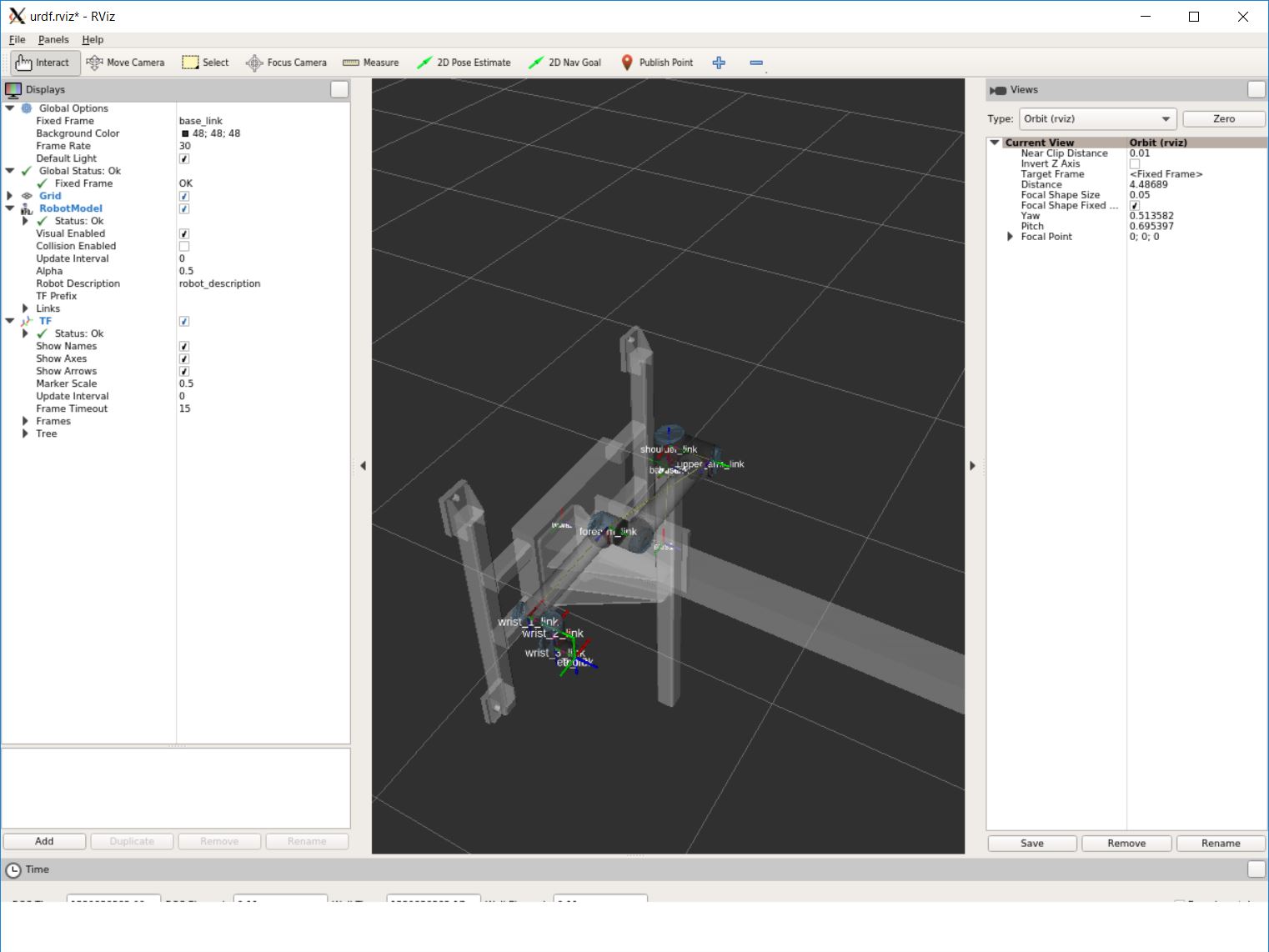
This shows the model turned, but no worries. It is only because the default
value for the global fixed frame is base_link which is not correct in our case.
Under Global Options > Fixed Frame > change base_link to tower or
world and press save.
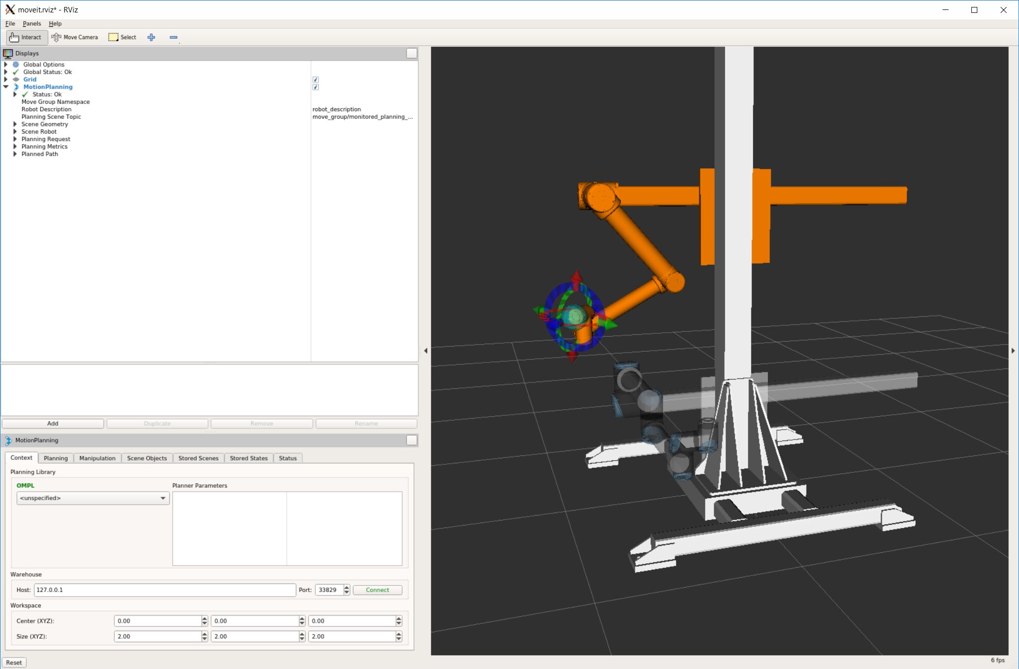
Then you should see something like that:
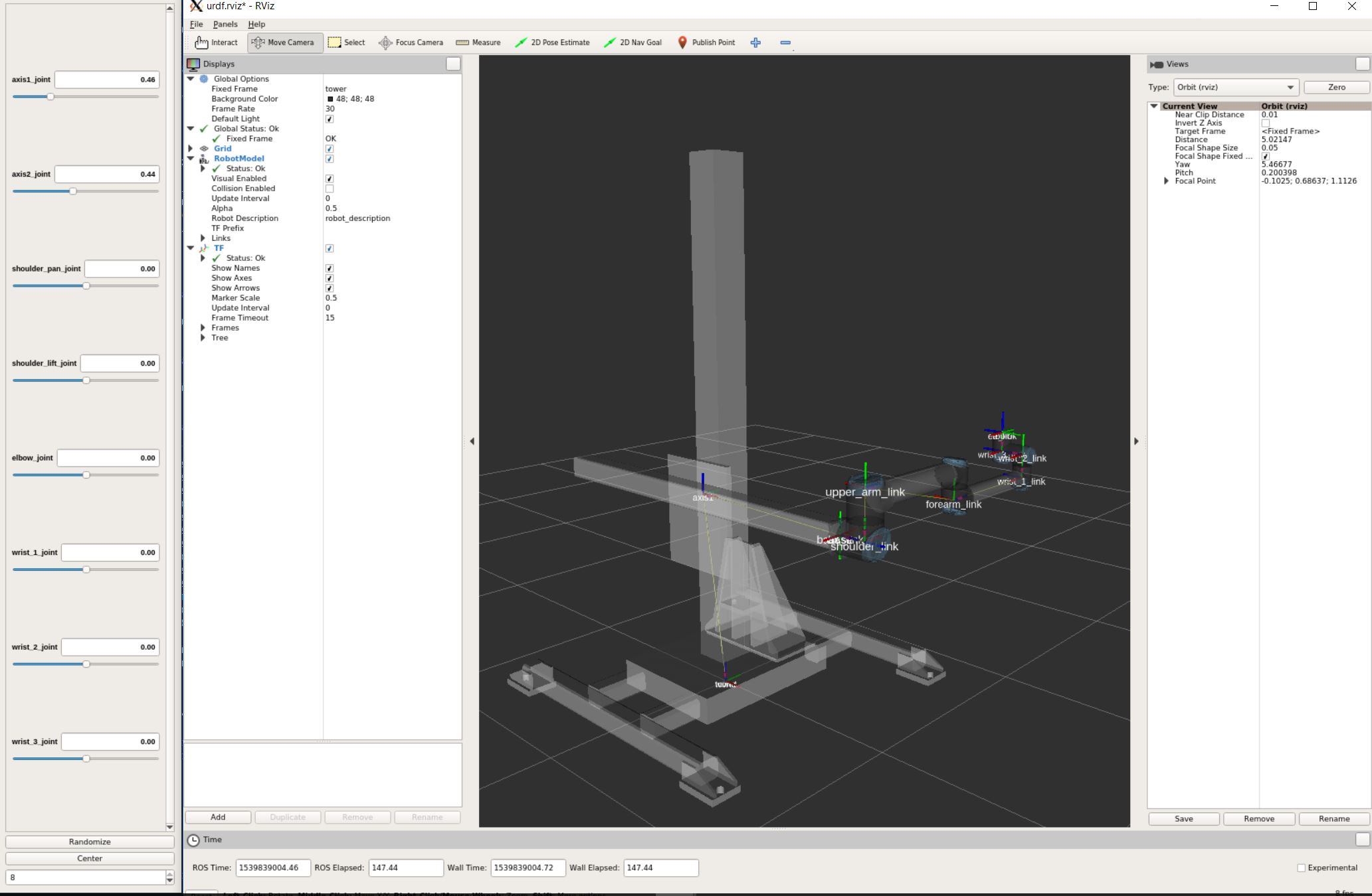
Screenshot of RViz showing the ur10 on the tower.
You can play with the sliders on the side to move the elements and check if all is fine.
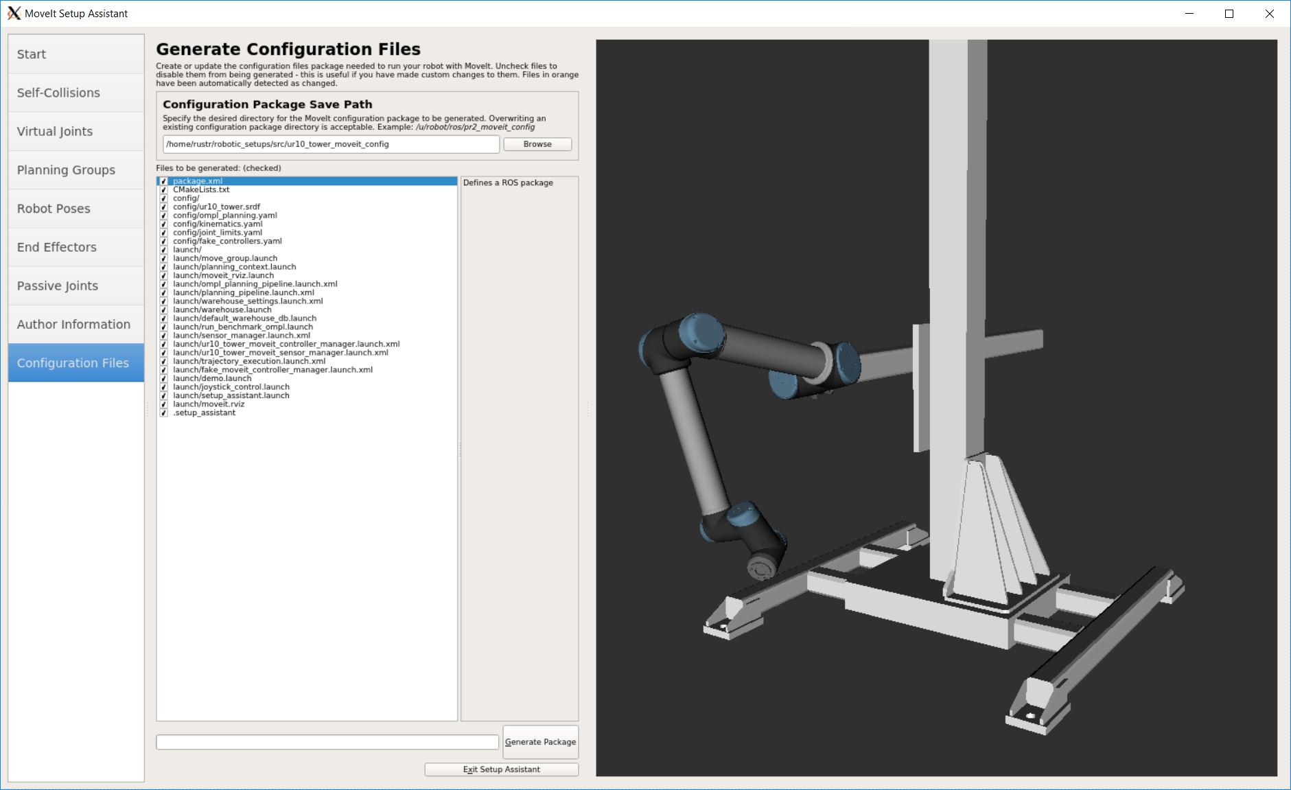
And later create a MoveIt! package from it.